Continue to Site

Welcome to EDAboard.com

Welcome to our site! EDAboard.com is an international Electronics Discussion Forum focused on EDA software, circuits, schematics, books, theory, papers, asic, pld, 8051, DSP, Network, RF, Analog Design, PCB, Service Manuals... and a whole lot more! To participate you need to register. Registration is free. Click here to register now.

please help me in this 8 watts audio amplifier circuit diagram

Status
Not open for further replies.

analyndalin

Newbie level 6
Joined
Aug 3, 2010
Messages
12
Helped
2
Reputation
4
Reaction score
2
Trophy points
1,283
Location
philippines
Activity points
1,356
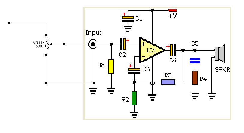
what value of potentiometer will i use for the volume control of this audio amplifier circuit and in what place will i connect that?

37_1298472721.gif


thank you
 

Because the c2 and r1 Functioning as "hi_past filter"
it is a Mistake adding Logarithmic Taper Potentiometer parall whit r1
my suggestion is to add the attachet circut
https://obrazki.elektroda.pl/59_1298496376.jpg
it will solve that case
With respect
Gabriel
 
C2 and R1 do not function as a high pass filter.
The schematic gabrielweto suggests adds a unity gain buffer ahead of the power amplifier. It has an unusual bias arrangement, without knowing what the ICs are its difficult to say whether it would do anything at all. It certainly won't work with most common amps.

Do what Alex suggests, you might be able to remove or increase the value of R1.

Brian.
 
No values are shown but I would add a potentiometer in parallel with R3, nearly the same value as R3 to reduce gain.
 
Last edited:
you ar right it is Definitely not a high passt filter
i wase too hasty :( sorry
( Filter Circuits with Capacitors )
anyway
Because the c2 block the DC current ther is no effect Between the amplifiers
the gain of the first amplifier is one, that mans ther is no effect on the general amplification
On the other hand it buffer between the Potentiometer and r1, the Outcome is no effect on each other
i think it is the best solution
from my experience its going to work very good
With respect
Gabriel
 
It depends on the type used for U1A, the vast majority of amplifiers will not work in this configuration, the output at pin 4 will be stuck at 0V and only extreme distortion may get through. Ideally, you want pin 4 to be sitting at half the supply voltage and the only ways to do that is to use a split power supply (positive and negative) or lift pin 1 to half supply.

Brian.
 
Because the c2 block the DC current ther is no effect Between the amplifiers

. . . . from my experience its going to work very good
It is because there is NOT a capacitor to block DC between the potentiometer and the buffer amplifier, (as well as no bias) that it will NOT work. It is not normal to introduce a unity-gain buffer amplifier unless there is a reason for it (such as to maintain a low impedance output). In this case there is not a reason for a buffer stage. If there was a need, it would be before the potentiometer.

@analyndalin
The simple answer proposed by alexan_e is the correct answer to your needs.
 

betwixt you'r right
tank you
i dont understand what DXNewcastle mean about "It is because there is NOT a capacitor to block DC between the potentiometer and the buffer amplifier"
can you explan mor about that ?

Gabriel
 

i dont understand what DXNewcastle mean about "It is because there is NOT a capacitor to block DC between the potentiometer and the buffer amplifier"
In your circuit, the DC conditions on the non-inverting input (Pin 1 of U1A) are grounded via the potentiometer.
0 volts on the non-inverting input will produce 0 volts on the output.
So, any audio signal will be an AC signal superimposed on the static DC condition of 0 volts. That would, for example, be a small signal with instantaneous voltages in the range between +2 volts and -2 volts.
The pre-amplifier will be incapable of producing that AC signal at its output becuase it does not have a power supply which provides negative voltages. It could only amplify the positive half-cycles, and even these are going to be poorly controlled close the 0 volts supply voltage. As Betwixt stated, the pre-amplifier will only be capable of producing extremely distorted audio.

If you had a reason to put a pre-amplifier before the power amplifier, then its DC must be biased to (approximately) half the suplpy voltage.
But the point I was trying to make to you was that a designer would only include a buffer amplifier into a circuit if it was going to achieve something useful. In this case, it has no purpose.
 
tank you friend's
i learn from you a lot
tanks again

Gabriel

By the way
can sombody help me with orcad layout
the autoroute is disabel in the dropdown list ( you can see it in the attacht fike)
 

Attachments

  • Desktop.rar
    398.7 KB · Views: 112

hi
use for vol 50k and for trbl and base 50k and for balance 100k


use for vol 50k and for trbl and base 50k and for balance 100k
Is this post some sort of spam ? Is this a person?

There is NOWHERE in the circuit shown to provide controls for 'trbl' (treble) or 'base' (bass) or 'balance'. These would require a lot more circuitry than shown in the scematic, and the circuit values would have to justify these arbitrary control values. More importantly, there was nothing in the OP's question to suggest that they were required.

As for the original question, it was answered more usefully in the first reply (its the logarithmic scale that matters more than the resistance - thanks to alexan_e)
 
Last edited:

Status
Not open for further replies.

Part and Inventory Search

Welcome to EDABoard.com

Sponsor

Back
Top