guangyu
Newbie level 4
Hi,
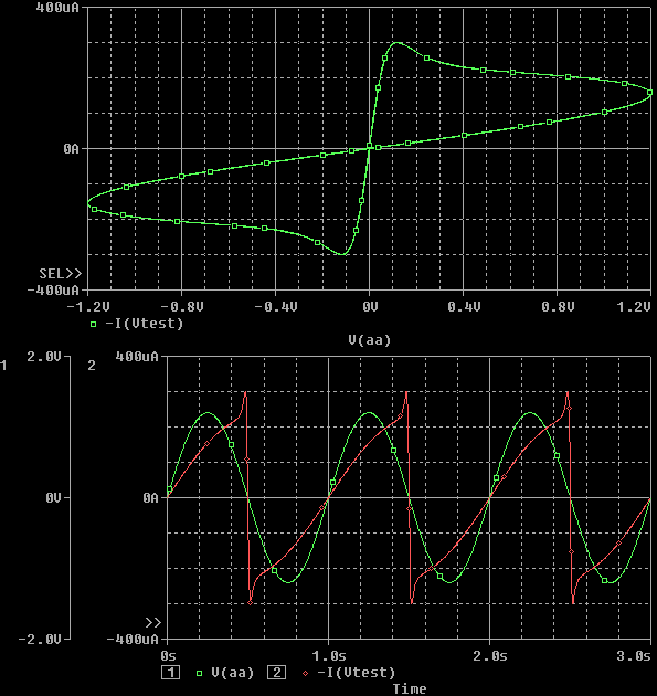
Has anyone used a spice model of memristor? I am trying to use the model proposed in BIOLEK's paper (https://www.radioeng.cz/fulltexts/2009/09_02_210_214.pdf) in LTspice. There is no error, but I couldn't observe any memresistive feature of the device. I assume this model works on Pspice since the paper claims so. Does function SDT() supported in LTSpice? Or is it because of something else?
The code is pasted here:
* HP Memristor SPICE Model
* For Transient Analysis only
* created by Zdenek and Dalibor Biolek
**************************
* Ron, Roff - Resistance in ON / OFF States
* Rinit - Resistance at T=0
* D - Width of the thin film
* uv - Migration coefficient
* p - Parameter of the WINDOW-function
* for modeling nonlinear boundary conditions
* x - W/D Ratio, W is the actual width
* of the doped area (from 0 to D)
*
.SUBCKT memristor Plus Minus PARAMS:
+ Ron=100 Roff=16K Rinit=11K D=10N uv=10F p=10
***********************************************
* DIFFERENTIAL EQUATION MODELING *
***********************************************
Gx 0 x value={ I(Emem)*uv*Ron/D^2*f(V(x),p)}
Cx x 0 1 IC={(Roff-Rinit)/(Roff-Ron)}
* Raux x 0 1T
* RESISTIVE PORT OF THE MEMRISTOR *
*******************************
Emem plus aux value={-I(Emem)*V(x)*(Roff-Ron)}
Roff aux minus {Roff}
***********************************************
*Flux computation*
***********************************************
Eflux flux 0 value={SDT(V(plus,minus))}
***********************************************
*Charge computation*
***********************************************
Echarge charge 0 value={SDT(I(Emem))}
***********************************************
* WINDOW FUNCTIONS
* FOR NONLINEAR DRIFT MODELING *
***********************************************
*window function, according to Joglekar
.func f(x,p)={1-(2*x-1)^(2*p)}
*proposed window function
;.func f(x,i,p)={1-(x-sttp(-i))^(2*p)}
.ENDS memristor
Xmemrist aa 0 memristor
Vtest 0 aa SIN(0 1.2V 1 0 0 0)
.tran 0.1s 3s
.option post
.end
Thanks,
-Guangyu
") .
.