Continue to Site

Welcome to EDAboard.com

Welcome to our site! EDAboard.com is an international Electronics Discussion Forum focused on EDA software, circuits, schematics, books, theory, papers, asic, pld, 8051, DSP, Network, RF, Analog Design, PCB, Service Manuals... and a whole lot more! To participate you need to register. Registration is free. Click here to register now.

7805 variable regulator

Status
Not open for further replies.

themaccabee

Full Member level 4
Joined
Apr 1, 2007
Messages
201
Helped
6
Reputation
12
Reaction score
6
Trophy points
1,298
Activity points
3,003
Hi,

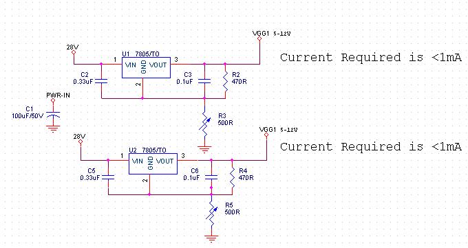
Im planning to use a 7805 to get a variable voltage regulator for the gate supply for an amplifier.
Digikey Part Number:MC7805BDTRKOSCT-ND

The input voltage is 28VDC
The output should be adjustable 5-12VDC, current <<1mA
So im hoping that the power dissipation (28-5)*1mA will be tolerable.

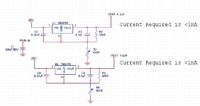
Im attaching a circuit i ve created for the same..


Ive some doubts here

1) the capacitors C2,C3,C5,C6 shall i connect it to the circuit ground or to IC 2nd Pin GND.?

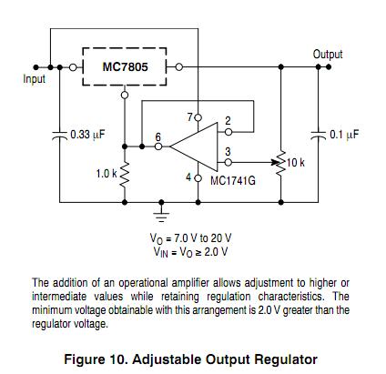
2) Ive got a data sheet mentioning an opamp buffer in between the pot & the GND pin.What is its functionality & is it required.
90_1294727131.jpg


3) How the regulation (particularly line regulation ) will be affected in this configuration?Can we do something to improve it.

Regards
Steve
 

Attachments

  • MC7800-D(2).PDF
    289.5 KB · Views: 95

Intead using 2 IC's the longer way, go simpler with just one three terminal Variable volatge regulator, the LM317. Hav emore info on the datasheet.
Cheers
 

Warning - short circuiting the output of harii74's schematic will probably destroy the transistor and could leave you with full input voltage at the output terminal.
I would go with Pranam77's suggestion and use an LM317. With a current of less than 1mA you could even use an LM741 and zener diode arrangement!
Brian.
 

For higher current, Instead of using new IC, in datasheet itself they have given PNP based higher current circuit, which is very useful as well as simple..
@harii74, even circuit what you have given looks good for me but it will have all the power dissipation across single transistor while in datasheet power dissipation will be shared by regulator IC & Transistor for higher current applications.
 

7805 is not stable on such a big voltage difference plus remember about power dissipation on IC

+1 for LM317
 

I don't think power dissipation is an issue when the load current is less than 1mA !
In fact I would be inclined to bleed some extra current into an additional load resistor to minimize the effects or leakage in the regulator.

Brian.
 

Please find my attachment. I have drawn this circuit only for this post.
I can see another difficulty with harii's design:- The estimates of Vout are correct at the 2 extremes of the variable potentiometer VZ1, but will be poorly controlled at intermediate positions.
In fact, the actual voltage on the Reference pin of the 7805 (pin 2) could vary as the current flowing through the resistor varies. The output Vout will change as pin 2 changes.

The LM317 is intended for use as a Variable Regulator.
 

In view of the small current demand, perhaps a shunt regulator like the TL431A would be the best solution and they are very inexpensive.
The data sheet has sample circuits and calculations to adjust the output voltage.
Brian.
 

Hello all, of course all are correct.
I suggested this to Theme, because he needs output from 5V to 12V. I strongly believe that it is highly sensitive to short circuit.Is it possible in LM317?
Instead of NPN in the circuit, PNP could be used but need small change in connection.
 

If you current consumption is less that 500mA then I suggest you use lm317 it is more reliable.
 

There is an interesting potential fault condition that one should be aware of when using the LM317. If the program resistor path opens while power is applied, the circuit will attempt to drive a nearly infinite current to the output, limited only by the supply voltage and the internal protection circuit. In other words; don't disconnect the resistor with the power on while breadboarding!

**broken link removed**

http://www.fairchildsemi.com/ds/LM/LM317L.pdf

http://www.st.com/stonline/products/literature/ds/2168/lm317l.pdf

http://www.onsemi.com/pub_link/Collateral/LM317L-D.PDF

http://www.utc-ic.com/spec/LM317L.pdf
 
hello everyone

i want to use voltage dividers with 7805 and 7812

I have attached the schematic here.

Is it possible to use divider like this with voltage regulator.?
 

Attachments

  • divider_regulator.jpg
    divider_regulator.jpg
    9.9 KB · Views: 113

How much current output do u want for the final 7805 regulator??
 

That's is the question?What is your maximum current needed from the output 5v?
 

i want to use voltage dividers with 7805 and 7812
. . . .
Is it possible to use divider like this with voltage regulator.?
As others have said, you will need to specify the maximum current expected at the output.
However, the use of a potential divider in the way you have calculated the resistors is faulty. You have assumed that the voltage at the junction of the two resistors is R2 / ( R1 + R2 ). (I have assumed that R2 is the resistor to ground).
When current flows through your circuit, the current flowing through the regulator is in parallel with R2, so the voltage ratio changes. You will always have less voltage on the input to the regulator than you intended.
It is better to let the regulator adjust the voltages and not a resistor-divider. Resistors are more appropriate for controlling current.
If you need to reduce the input voltage before the regulator, and you let us know the maximum current, we can help in calculating a voltage divider which will help reduce that input voltage without loosing the required voltage.
 
thank you DXNewcastle,

i need the output current of 1mA at both op pins i.e for 12V and for 5 V
 

i need the output current of 1mA at both op pins i.e for 12V and for 5 V
1. You must always provide a higher voltage at the input to a 78xx regulator than its output voltage. This should be a minimum of 2.5 volts higher than the output voltage. For example, your voltage dividers would be calculated to provide 7.5 volts for the input to the 7805.

2. 1mA is a very small current, so it will not affect the value of the ground connection of the voltage divider by very much.

3. You do not need to use the 7812 before the 7805 unless there is more circuit which you have not shown us. A 7805 will tolerate up to 22volts on its input.

It follows from these three points that you do not need to use any voltage dividing resistors at all, just a 7805 between 22v input and 5v output, plus local decoupling capacitors on the input and output. However, if you do need a 12 volt supply, you can use the 2 regulators in the circuit you posted, but without any voltage dividing resistors.

If you needed these resistors because you want to provide some current limiting, then you may use a resistor on the input pin of the first regulator - I suggest approximately 7k5 to reduce the voltage if the current exceeds 2mA, but there are many more effective current limiting circuit arrangements using a regulator and power transistor available.

I hope this helps
 
I think you need LP2951 - adjustable LDO regulator from 1.24 to 29V. It's in small SMD SOT23 package - www.national.com/ds/LP/LP2950.pdf

It's cheap, it's compact and completely fits to what you need.
 

Status
Not open for further replies.

Similar threads

Part and Inventory Search

Welcome to EDABoard.com

Sponsor

Back
Top