Continue to Site

Welcome to EDAboard.com

Welcome to our site! EDAboard.com is an international Electronics Discussion Forum focused on EDA software, circuits, schematics, books, theory, papers, asic, pld, 8051, DSP, Network, RF, Analog Design, PCB, Service Manuals... and a whole lot more! To participate you need to register. Registration is free. Click here to register now.

[SOLVED] Plotting the cutt off frequency of transfer function

Status
Not open for further replies.

oshaye3

Member level 3
Joined
Aug 4, 2010
Messages
62
Helped
0
Reputation
0
Reaction score
0
Trophy points
1,286
Location
london
Activity points
1,822
Dear all,

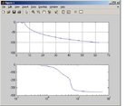
Can someone identify the error in my code, I wanted to plot the frequency response of this chebyshev filter with the cutt off frequency. It is giving error. Any response!

Code:

n = input('\n Enter the order of Chebyshev filter : ');
eibsln = input('\n Enter the ripple factor of the passband : ');
fc = input('\n Enter the Cutt off frequency for your filter:');
ripples=10*log(1+ eibsln.^2);
Bw=2*pi*fc


Cheb_P=ChebyshevPoly(n)
T_NB2=conv(Cheb_P,Cheb_P)
T_NB2EPS= (eibsln^2).* (T_NB2)
T_NB2EPS2=T_NB2EPS;
T_NB2EPS2(end)=T_NB2EPS(end)+1
% Get the poles
thepolesOmega=roots(T_NB2EPS2);
thepoles=j*thepolesOmega
thepoles_s=thepoles* Bw


hh =find(real(thepoles_s)<0)
stpoles = thepoles_s(hh) % Stable Poles
den1 = poly(stpoles)
den2 = real(den1)
H1 = tf(1,den2) % Transfer function
A=den2
p=polyfact(A)
p_size=ones(size(p))
num = num2cell(p_size);
H2= tf(num,p)
grid on

numer=1;
[numer,den2]= cheby1(n,ripples,1,'s') % Wc = 1 [rad/s]
ww = logspace(-1,1);
h_norm = freqs(num,den2,ww)
mag = abs(h_norm);
mag = 20*log10(mag);
phase = unwrap(angle(h_norm))*180/pi;
% to display axis with fc [Hz]
f_ww= ww* 2*pi ;
subplot(2,1,1), semilogx(f_ww,mag)
subplot(2,1,2), semilogx(f_ww,phase)


Results:
Error in ==> auto_cheby_testing at 38
h_norm = freqs(num,den2,ww)
 

Ho oshaye3,

in the line

h_norm = freqs(num,den2,ww)

num should be a vector, but it was defined as a cell array.
I guess you intended to write

h_norm = freqs(numer,den2,ww)

instead of

h_norm = freqs(num,den2,ww)

The former line (with numer in lieu of num) should work.
Regards

Z
 
Hi Zoro,

Thanks for spotting the error. I have simulated the program, but is not giving the cut off frequency. I have attached the result of the simulation, how can i incorporate the bandwidth properly to get the cut off frequency.

I ought to get 2500 as cut off freq.

Thanks
 

Attachments

  • simu_4th.jpg
    simu_4th.jpg
    36.1 KB · Views: 111

Hi oshaye3,

the second time the polynomial is calculated, it is done for Wn=1.
The lines

[numer,den2]= cheby1(n,ripples,1,'s') % Wc = 1 [rad/s]
ww = logspace(-1,1);

should be changed by

[numer,den2]= cheby1(n,ripples,Bw,'s');
ww = logspace(-1,1)*Bw;

Regards

Z
 
Zoro, Thanks for the response. It is plotting the cut off frequency as specified. However, if you can help me see what is wrong in this code. I am trying to calculate the value of components from my transfer function in each 2nd order of the TF. this is the code and the error it gives. suppose I want 4 order . it plott the cut off, but to align the code to derive my component value is not correct. see below! I am really sorry for asking questions

code:

p=polyfact(A)
p_size=ones(size(p))
num = num2cell(p_size);
H2= tf(num,p)
grid on

numer=1;
[numer,den2]= cheby1(n,ripples,Bw,'s') % Wc = 1 [rad/s]
ww = logspace(-1,1)*Bw;
h_norm = freqs(numer,den2,ww)
mag = abs(h_norm);
mag = 20*log10(mag);
phase = unwrap(angle(h_norm))*180/pi;
% to display axis with fc [Hz]
f_ww= ww/(2*pi);
subplot(2,1,1),plot(f_ww,mag)
grid on
subplot(2,1,2), semilogx(f_ww,phase)


R1 = 10 % kohms
R4 = R1/p(3) % kohms
R3 = R1*R4/(R1+R4) % kohms
C5 = p(2)/(2*R1) ; C2 = p(1)/(R1*R3*C5);
C5 = 1e6/Bw*C5 % nF
C2 = 1e6/Bw*C2 % nF

Results:
Transfer function:
1
-------------------------------------------------------------
s^4 + 1.687e005 s^3 + 9.695e010 s^2 + 9.722e015 s + 1.217e021


A =

1.0e+021 *

0.0000 0.0000 0.0000 0.0000 1.2175


p =

[1x3 double] [1x3 double]


p_size =

1 1


Transfer function from input 1 to output:
1
----------------------------
s^2 + 4.94e004 s + 7.478e010

Transfer function from input 2 to output:
1
-----------------------------
s^2 + 1.193e005 s + 1.628e010

error :

Index exceeds matrix dimensions.

Error in ==> auto_cheby_testing at 50
R4 = R1/p(3) % kohms
 

How is the function "polyfact()"?
It seems to return a 2-element cell array, where each component is a 1x3 array.
Regards

Z
 

Thanks Zoro! This is the polyfact code: It is another function within the program. here is the code: Many thanks

function q = polyfact(A)
r = roots(A);
l=1;k=1;
while k <= length(r)
if isreal(r(k))
q(l) = {[1,-r(k)]};
else
q(l) = {[1,-2*real(r(k)),r(k)*r(k+1)]};
k=k+1;
end
l=l+1;k=k+1;
end
return
 

OK, the function returns a cell array of vectors, one member for each single real pole of pair of complex poles.
As you synthesize a 2nd order section for each pair of poles, for the first one you should replace p(3) by p{1}(3), and analogously for the others i order to obtain R1, R4, R3, C2 and C5.
For the second section, use p{2}(3), etc.
Do you understand why?

Regards

Z
 
Thanks, I do not understand how it is as you have defined it. Any explanation, please let me know

Regards

Michael
 

Zoro, Thanks for your response. I have put the value in the equations, but it gives me wrong values for components resistor should be in mohms and capacitors in kF+. Please how can do that? I put the code and result down:

R1 = 10000 % the value set.
R4 = R1/p{1}(3)
R3 = (R1*R4/(R1+R4))
C5 = (p{1}(2)/(2*R1));
C2 = (p{1}(1)/(R1*R3*C5));
C5 = Bw*C5
C2 = Bw*C2

R1b = 10000 % the value set.
R4b = R1b/p{2}(3)
R3b = (R1b*R4b/(R1b+R4b))
C5b = (p{2}(2)/(2*R1b));
C2b = (p{2}(1)/(R1b*R3b*C5b));
C5b = Bw*C5b % uF
C2b = Bw*C2b % uF

Results:
R1 = 10000
R4 =1.1219e-007
R3 =1.1219e-007
C5 =8.4062e+005
C2 = 1.0465e+008
R1b =10000
R4b =5.1699e-007
R3b =5.1699e-007
C5b =2.0294e+006
C2b =9.4068e+006

Thanks
 

Thanks Zoro,

I have founf it out, now my step is to convert my transfer function to digital. I am considering two methods. 1. bilinear, but not that ok for or z transform using impulse response. Please suggest good way to convert my program to digital

Cheers,
 

Zorro, ok suppose I have odd order (3) transfer function as pasted below: how should i define the first order section in my program. If I want to use conditional statement to fit my program, it gives error. The last transfer function of any odd order is always first order section. If i use conditional statement as If H2(end)=what?

Please any contribution. cheers

Transfer function from input 1 to output:
0.1774
-----------------------
s^2 + 0.2986 s + 0.8392

Transfer function from input 2 to output:
0.1774
----------
s + 0.2986
 

Hi again, Michael

The first-order section must have a different topology, with a single capacitor instead of two.
I don't understand "If i use conditional statement as If H2(end)=what?".
Regards

Z
 

Thanks Zoro, I know that we need to use different topology for first order section. I am asking how can I write the code so that it calculate for component in first order section.I will as below put the code below and results. As we name the second order section as P{1)(1)......... how should i define the first order to calculate my components value. Many thanks.
code:

% 2nd order section

pp1=(p{1}(1)/p{1}(3));
pp2=(p{1}(2)/p{1}(3));
pp3=(p{1}(3)/p{1}(3));
up=gain_c/p{1}(3)
Q=1/(fsf*norm)
C4 = 1e-09 % the value set.
C1 =( C4/10^(dc/(20)))
C3 = (C1*C4/(C1+C4))
R5 =pp2/(2*C1);


R2 = pp1/(C4*C3*R5);
R5=1/Bw*R5
R2=1/Bw*R2


% 4th order section

pp1b=(p{2}(1)/p{2}(3));
pp2b=(p{2}(2)/p{2}(3));
pp3b=(p{2}(3)/p{2}(3));
normb=(p{2}(2)/(p{2}(3)))
C4b = 1e-09 % the value set.
C1b = (C4b/10^(dc/(20)))
C3b = (C1b*C4b/(C1b+C4b))
R5b =pp2b/(2*C1b); R2b = pp1b/(C4b*C3b*R5b);
R5b=1/Bw*R5b
R2b=1/Bw*R2b

results
R1 =

10000


R4 =

7.9433e+003 R3 =4.4269e+003 C5 =5.6635e-011
C2 = 4.8157e-009
??? Attempted to access p.Öell(3); index out of bounds because numel(p.

Error in ==> new at 81
pp1b=(p{2}(1)/p{2}(3));
 

Zoro, I hope you are fine. I am trying to arrange this transfer funcion but it gives me error. look at the result and error. How can I arrange it so that the first order become last in the transfer function PLEASE SEE BELOW. ANY LOGIC THANKS

Transfer function from input 1 to output:
1
-----------------
s^2 + 0.618 s + 1

Transfer function from input 2 to output:
1
-----
s + 1

Transfer function from input 3 to output:
1
-----------------
s^2 + 1.618 s + 1

??? Undefined function or method 'sort' for input arguments of type 'tf'.

Error in ==> mbutter at 43
H2=sort(H2,'descend')
 

Status
Not open for further replies.

Part and Inventory Search

Welcome to EDABoard.com

Sponsor

Back
Top