Continue to Site

Welcome to EDAboard.com

Welcome to our site! EDAboard.com is an international Electronics Discussion Forum focused on EDA software, circuits, schematics, books, theory, papers, asic, pld, 8051, DSP, Network, RF, Analog Design, PCB, Service Manuals... and a whole lot more! To participate you need to register. Registration is free. Click here to register now.

bipolar stepper motor driver using l297 and mosfet h bridge..........

Status
Not open for further replies.

jit_singh_tara

Full Member level 6
Joined
Dec 22, 2006
Messages
325
Helped
9
Reputation
18
Reaction score
4
Trophy points
1,298
Location
Delhi , India
Activity points
4,293
Hello friends,
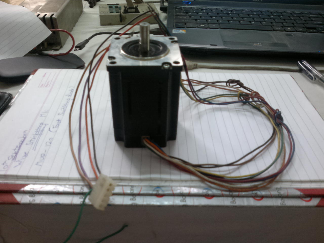
I am buiding this circuit that uses a stepper motor or rating 4.7 amp / phase .
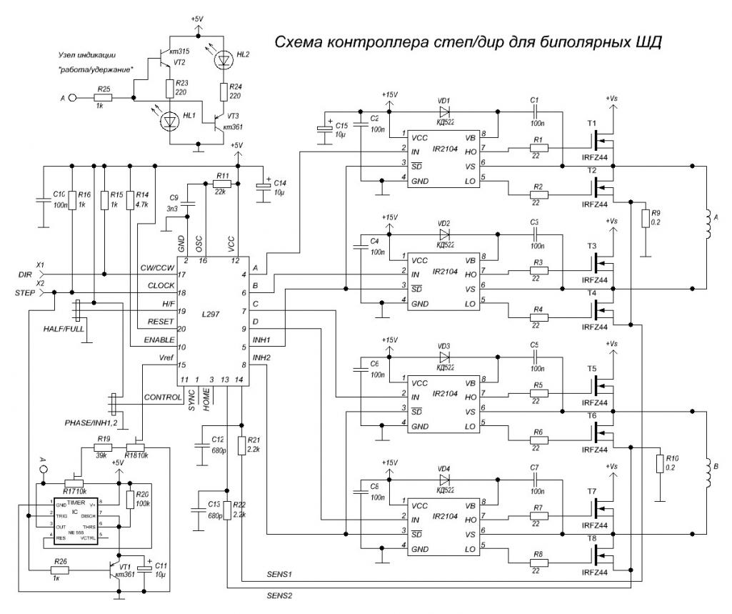
I want to build a circuit that uses l297 and mosfet hbridge to drive it .Please suggest how to proceed.
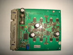
i have a damaged pcb which does exactly the same job.The components used are:

HD14572 - 1
74HC00 - 2
74HC14 - 1
HEF4049 - 2
SUD50N06 - 4
SUD50P06 - 4
L297 - 1


2.5 AMP FUSE
1 TRIMPOT 10K
220U F 63 V 5 CAPACITORS ELECTROLYTIC

PLease help me with the circuit :how to make it.The technical knowhow how to begin.This is a very useful circuit for driving bipolar stepper motors of high torque ...please help complete it as it will benefit us all.
 

Attachments

  • DSC00848.JPG
    DSC00848.JPG
    2.6 MB · Views: 306

What kind of step motor do you have? How many wires?

Not all step motors requires H-bridge in order to drive. If yours have 5 or 6 wires, four transistors should be enough (pluss aditional software/driver circuit).
 
Not all step motors requires H-bridge in order to drive.
The driver board is obviously intended for a bipolar stepper motor and implements H-bridges.

PLease help me with the circuit :how to make it.
There are more circuit details involved than just listing the ICs. You can try to find out the exact circuit of the board, the wiring and all small SMD transistor types and passive component values. Or design a functional equivalent circuit from different parts.
 
Well i am using 8 lead stepper motor and using it in bipolar parallel config.

well so far i know is that l297 is for generating the signals for driving the h bridge.one ic is hex inverter schmitt trigger for giving clean pulses .Basically i want to know how is mosfet being driven in h bridge configuration .The components smd diode and resistors are for driving the mosfets and its protection ,but i dnt know the complete details .Please help ......
 
Last edited:

Please reply to this thread ....i am waiting friends ....please let me know if anyone has done anything similar like this before....
 

please let me know if anyone has done anything similar like this before....
Hundreds of designs are implimented and used regarding driving of stepper motors. If some one has done similar design, you cannot gain anything from that. Just stick to your design, post your cicruit, and your problems what you face, and expect replies. Take challenges and make it work. Sucess will be yours. Then if you think of sharing your final design here, Nothing like It.
Cheers
 
Hi... my this schematic can help you
 

Attachments

  • schematic L293D.pdf
    143.6 KB · Views: 361

dear friends ,

i am replying to this post after a long time , i apologise for not being able to reply...
Once again i would like to start from scratch in making a bipolar stepper motor driver ,l297 and mosfet h bridge based.

So far i have tested the pulse generating part l297 .

I want to use the sequence generated by it to drive a heavy stepper motor using mosfet h bridge and mosfet driver ir2104 .
I would be thankful if you could share some of your experience regarding this.

Please let me know about the power section .i have a sample circuit based on which i want to build this circuit.
I have no idea regarding the mosfet and ir2104 ,plz share some experience .


i am driving this motor:


View attachment 2 Phase - PSM57 Series.pdf


Thanks and regards
Jitender Singh
 
Last edited:

your schematic uses all N-mosfet H bridge so the high side mosfet gates have to be driven with a voltage higher about 10-12v compared to the drain, you can check https://www.edaboard.com/threads/213663/#post903721 for the explanation.

There are a couple of ways to do that but in your case the bootstrap method is used which is accomplished by D1 and C1 (as an example for the top IR2104).
The bootstrap method charges a capacitor (C1) to the supply voltage level and then when the high side mosfet turns on the capacitor voltage works like a battery to provide to the gate the source voltage + Vcapacitor so the proper Vgs is accomplished.
Take a look a my post https://www.edaboard.com/threads/214299/#post907033

Apart from generating the appropriate voltage to drive the high side mosfet gates the driver IR2104 has also a proper high current output stage that can charge/discharge the mosfet gates fast for fast switching and low switching losses on the mosfets.

Alex
 
Status
Not open for further replies.

Part and Inventory Search

Welcome to EDABoard.com

Sponsor

Back
Top