lowrainer
Newbie level 4
Hello,
I designed a forward converter for university needs. Now I am testing the converter and I have some difficulties in seeing where my problem comes from.
First of all.
Uin=12V Uout=100V Iout=1A
tr=128/5
UC3845 atm no control, it is running at full 50% duty cycle
L=approx 5,8mH
Lprim= 100mH ΔI=0.25A
The problem is:
After the Mosfet turned of, the voltage across the Mosfett should be 24V until the demagnitizing winding is demagnitized. Then the voltage across should be 12V. My measurement display a little simimlarity. First there is a voltage peak (which i tried to get rid of with a snubber...omg it is not working correctly), then the voltage breaks down and comes back to 12V. I don't understand why the voltage breaks down after the peak. it should stay around 24V.
Caused by the peak and "oscillation" my Mosfets gets thermally destroyed after a while. My snubber consists out of a fast rectifier diod in Series with a capacitor 0,47µF and a 5 parallel 82Ω resistors. The peak is about 52V high, therefore ΔU=28V which should be absorbed by the Snubber.
Can anybody help me with:
1. Why is the voltage breaking down after turning of the Mosfet?
2. What do I have to do that my Snubber is working correct?
Cheers
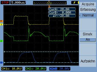
On the image you see 1. the clock (50kHz), 2. Umosfet (voltage across mosfet), 3. I1 ( current through primary winding rising up to around 28A)
I designed a forward converter for university needs. Now I am testing the converter and I have some difficulties in seeing where my problem comes from.
First of all.
Uin=12V Uout=100V Iout=1A
tr=128/5
UC3845 atm no control, it is running at full 50% duty cycle
L=approx 5,8mH
Lprim= 100mH ΔI=0.25A
The problem is:
After the Mosfet turned of, the voltage across the Mosfett should be 24V until the demagnitizing winding is demagnitized. Then the voltage across should be 12V. My measurement display a little simimlarity. First there is a voltage peak (which i tried to get rid of with a snubber...omg it is not working correctly), then the voltage breaks down and comes back to 12V. I don't understand why the voltage breaks down after the peak. it should stay around 24V.
Caused by the peak and "oscillation" my Mosfets gets thermally destroyed after a while. My snubber consists out of a fast rectifier diod in Series with a capacitor 0,47µF and a 5 parallel 82Ω resistors. The peak is about 52V high, therefore ΔU=28V which should be absorbed by the Snubber.
Can anybody help me with:
1. Why is the voltage breaking down after turning of the Mosfet?
2. What do I have to do that my Snubber is working correct?
Cheers
On the image you see 1. the clock (50kHz), 2. Umosfet (voltage across mosfet), 3. I1 ( current through primary winding rising up to around 28A)