Continue to Site

Welcome to EDAboard.com

Welcome to our site! EDAboard.com is an international Electronics Discussion Forum focused on EDA software, circuits, schematics, books, theory, papers, asic, pld, 8051, DSP, Network, RF, Analog Design, PCB, Service Manuals... and a whole lot more! To participate you need to register. Registration is free. Click here to register now.

UNDER VOLTAGE PROTECTION for inverter

Status
Not open for further replies.

shamil_my

Newbie level 3
Joined
Aug 3, 2010
Messages
3
Helped
0
Reputation
0
Reaction score
0
Trophy points
1,281
Activity points
1,299
Dear sirs,

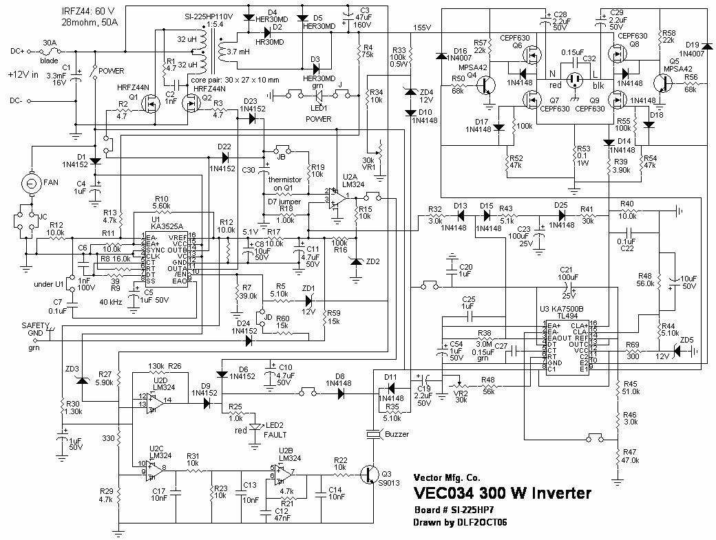
I have 500 watt inverter , so when the battery voltage drob or become low the internal fuse of inverter blowen and in most case one of mosfet transistor that switghing the 12vdc to high freq. is also damage,so please i need to put an protection to protect my inverter from this ,can any have an idea to solve this problem?

thanks,[/b]
 

U need to put an Opamp (comparator) in the Switching section of Input side, which will go shut down the switching of primary or supply to inverter section and shut down inverter...if u provide me with ur diagram of inverter, i might tell u where to fit the scheme, it will help in overvoltage protection also.
 
Hi,kindly attached your circute diagram if possible in other to desinge a suitable circute for your protections
 

thanks for reply,
the circuit diagram for my inverter is like this attached.
 

Hi, you mention that your that your mosfet get burnt any time your battery went low can you tell me the mosfet is it the high frequency side or the low frequency 50Hz,also D16 and D19 Suppose to be connected to your vcc
 

the mosfet is at high frequency side
 

I will need some time to study the Schematic of ur inverter, in the meanwhile what I can suggest is u put some comparator Opamps in the path of Error Amplifier pin of KA3525. I dont know much about 3525, but I have worked with 7500. but in my case, we stop the supply in auxiliary transformer which will stop further working of both push-pull as well as inverter section. I wil send u the page where u can find the scheme, and if implemented with same value of resistors, ur inverter should stop working when input voltaghe goes below 10.8V or above 14.4V.
 

Status
Not open for further replies.

Part and Inventory Search

Welcome to EDABoard.com

Sponsor

Back
Top