gres
Full Member level 4
Repeater PMR on ISD25
It's a simple but very useful device for radio fans.
Repeater base on ISD2560/75 or 90 chip. Lower record time means that sound quality is better, so the best choice would be 2560. System is controlled by PIC. To input signal goes from radio , is recording and playing, signals shorter ther 1s are ignore.
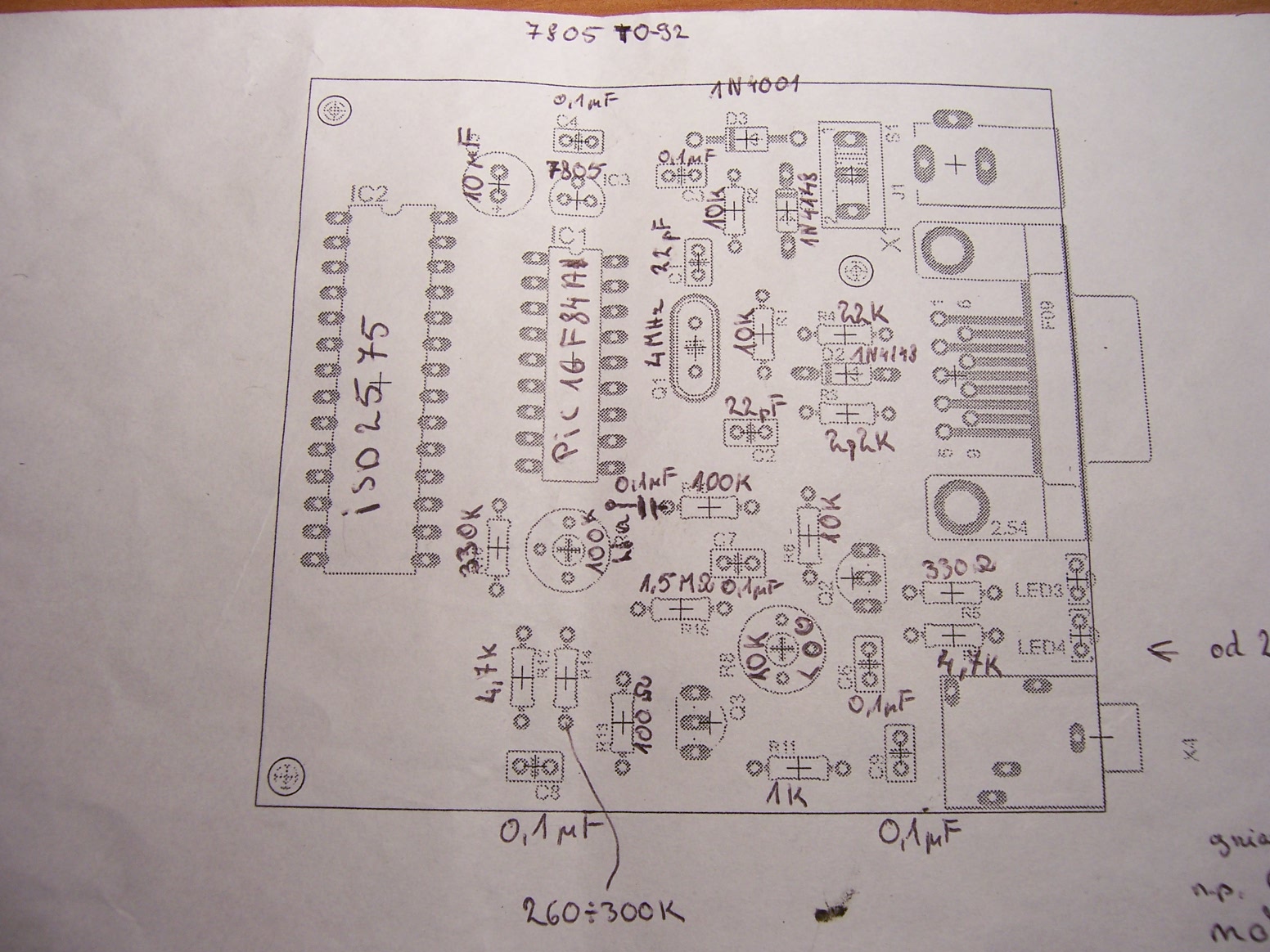
Elements description:
0,1 mikrofarad 7
22 pF 2 ceramic units
10 mikrofarads
Voltage stabilizer 7805 in TO-92 casing
1N4001 diode
1N4148 diode
10k 3 units
22k
2,2k
100k
330k
4,7k 2 units
1k
1,5 Mega ohm
330 ohm
100 ohm
260 - 300 ohm ( you need to take something from this range
Line potentiometer 100k ( it regulate recording signal level e.g. repeater will record only clear sound, or only noise )
Logarithmic potentiometer 10k ( modulate regulation while sending)
Quartz 4 MHz
Green led
Red led
Base with 28 legs ISD 2560/75/90
Base with 18 legs PIC16F84
PIC16F84
ISD2560/2575 or 2590
BC 549B 2 units
Most expensive is ISD system , rest is very cheap.
If after complete system can't start sending, you need to exchange R7 to 2,4k
System should be powered from 6 to 12V
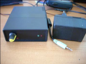
After start green led should blink twice.
When repeater is recording, green diode is on, when playing red is on.
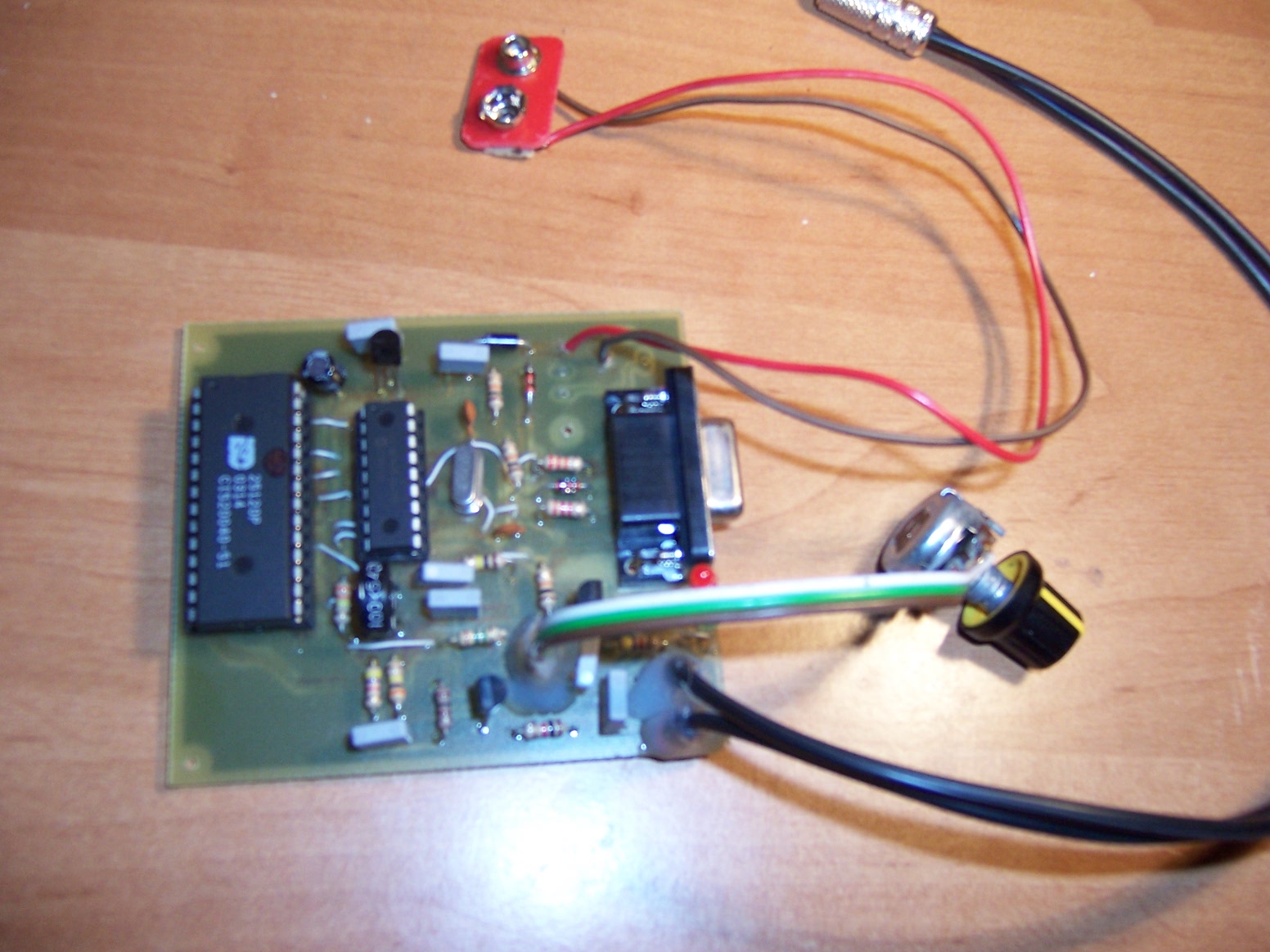
Elements at the board:
Here you can find software for recording, unfortunatly only 60 seconds. 75 and 90 i don't have but after had installed chip with longer recording time will stop after 60 sec.
**broken link removed**
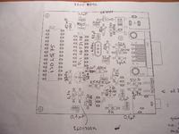
Board is ready to print.
"Zworki" means jumpers diagram
Diagram
All of this you can find at[url[http://www.elektroda.pl/rtvforum/topic1495036.html[/url]

It's a simple but very useful device for radio fans.
Repeater base on ISD2560/75 or 90 chip. Lower record time means that sound quality is better, so the best choice would be 2560. System is controlled by PIC. To input signal goes from radio , is recording and playing, signals shorter ther 1s are ignore.
Elements description:
0,1 mikrofarad 7
22 pF 2 ceramic units
10 mikrofarads
Voltage stabilizer 7805 in TO-92 casing
1N4001 diode
1N4148 diode
10k 3 units
22k
2,2k
100k
330k
4,7k 2 units
1k
1,5 Mega ohm
330 ohm
100 ohm
260 - 300 ohm ( you need to take something from this range
Line potentiometer 100k ( it regulate recording signal level e.g. repeater will record only clear sound, or only noise )
Logarithmic potentiometer 10k ( modulate regulation while sending)
Quartz 4 MHz
Green led
Red led
Base with 28 legs ISD 2560/75/90
Base with 18 legs PIC16F84
PIC16F84
ISD2560/2575 or 2590
BC 549B 2 units
Most expensive is ISD system , rest is very cheap.
If after complete system can't start sending, you need to exchange R7 to 2,4k
System should be powered from 6 to 12V
After start green led should blink twice.
When repeater is recording, green diode is on, when playing red is on.
Elements at the board:
Here you can find software for recording, unfortunatly only 60 seconds. 75 and 90 i don't have but after had installed chip with longer recording time will stop after 60 sec.
**broken link removed**
Board is ready to print.
"Zworki" means jumpers diagram
Diagram
All of this you can find at[url[http://www.elektroda.pl/rtvforum/topic1495036.html[/url]