abhaybonds
Newbie level 4
I tried making a ultrasonic transmitter and receiver using the information given in the following link **broken link removed**
I made the transmitter and reciever circuits. Both the circuits individually work fine i.e. the frequency of both the transmitter and reciever is shown to be 40 Khz when checked with oscilloscope at the appropriate points of the circuit as told in the link.
Even the output of the receiver circuit shows a high output at pin 8 of LM567 and when a step voltage of frequency 40khz is applied at the point of connection of ultrasonic receiver the output becomes low.
But when I connect the ultrasonic transmitter/transducer and receiver to the circuit I dont get the desired results.
Is it because I connectd the sensors in the opposite way i.e opposite polarity. Do these sensors have any polarity. If yes, could you please tell me the correct polarity . If no, what else could be the problem
Please help.
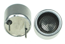
I have these kind of sensors http://obrazki.elektroda.pl/26_1264077135.jpg they have some black ring at one pole.
I made the transmitter and reciever circuits. Both the circuits individually work fine i.e. the frequency of both the transmitter and reciever is shown to be 40 Khz when checked with oscilloscope at the appropriate points of the circuit as told in the link.
Even the output of the receiver circuit shows a high output at pin 8 of LM567 and when a step voltage of frequency 40khz is applied at the point of connection of ultrasonic receiver the output becomes low.
But when I connect the ultrasonic transmitter/transducer and receiver to the circuit I dont get the desired results.
Is it because I connectd the sensors in the opposite way i.e opposite polarity. Do these sensors have any polarity. If yes, could you please tell me the correct polarity . If no, what else could be the problem
Please help.
I have these kind of sensors http://obrazki.elektroda.pl/26_1264077135.jpg they have some black ring at one pole.