Continue to Site

Welcome to EDAboard.com

Welcome to our site! EDAboard.com is an international Electronics Discussion Forum focused on EDA software, circuits, schematics, books, theory, papers, asic, pld, 8051, DSP, Network, RF, Analog Design, PCB, Service Manuals... and a whole lot more! To participate you need to register. Registration is free. Click here to register now.

is pic165877a is compatible with ir2110 gate driver

Status
Not open for further replies.

keklik

Newbie level 3
Joined
Dec 14, 2009
Messages
3
Helped
0
Reputation
0
Reaction score
0
Trophy points
1,281
Activity points
1,302
16f877a pwm no output

I have written a code below to produce a 20kHz pwm to create a sinus wave at 50 Hz by changing duty cycle.
When I run the program it gave me no out puts on RC1 and RC2 pins. I got just logic 0. But pin RC0 was always logic 1. I couldn't find what wrong is.
Here is the code:
Code:
#include <16f877a.h>     

#fuses XT,NOWDT,NOPROTECT,NOBROWNOUT,NOLVP,NOPUT,NOWRT,NODEBUG,NOCPD  

#use delay(clock=20000000) //crystal freq.
#use fast_io(c) //c port are outputs
void main()
{
   int i;
   int j=1; //just to sure not to get 0 at multiplication part
   setup_psp(PSP_DISABLED);                 
   setup_timer_1(T1_DISABLED);           
   setup_adc_ports(NO_ANALOGS);         
   setup_adc(ADC_OFF);                  
   set_tris_c(0x00);                  
   setup_CCP1(CCP_PWM);              
   setup_CCP2(CCP_PWM);             
   setup_timer_2(T2_DIV_BY_1,249,1);
   set_pwm1_duty(j);
   set_pwm2_duty(j);
   
      while(1)
   { 
    
    for (i=1;i<=100;i++) // 100 pwms at quarter of a sinus wave (first 5ms of sinus)
    {
    j=i*10;
    set_pwm2_duty(j);
    }
    
    for (i=100;i>=1;i--) // 100 pwms at quarter of a sinus wave (second 5ms of sinus)
    {
    j=i*10;
    set_pwm2_duty(j);
    
    for (i=1;i<=100;i++) // 100 pwms at quarter of a sinus wave(third 5ms of sinus)
    {
    j=i*10;
}
    set_pwm1_duty(j);
    }
    
    for (i=100;i>=1;i--) // 100 pwms at quarter of a sinus wave(forth 5ms of sinus wave)
    {
    j=i*10;
    set_pwm1_duty(j);
    }   
   
   }

    }
 

Re: 16f877a pwm no output

With some code changes, I figured out that if I use just set_pwm1_duty(j) or set_pwm2_duty(j) in code it looks like working.(I think Proteus can't show duty cycle changes, but shows %50 duty cycle pwm signal). So how can I use both of the pwm pins?
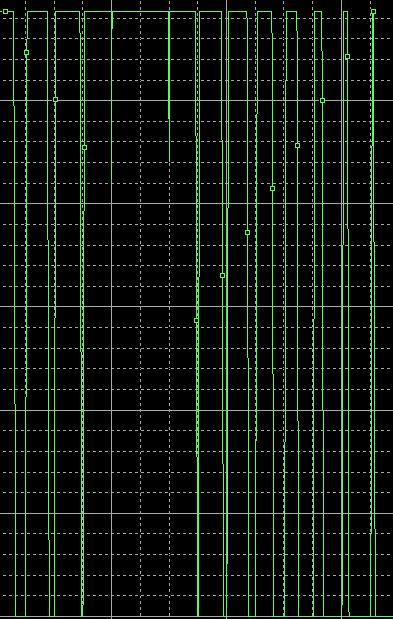
This picture shows the pwm signal I need to create:
66_1261775177.jpg
 

Re: 16f877a pwm no output

Hi,

You simply can't generate a sinusoidal PWM using this method.

In your for loops, you are updating the duty cycle several times before one period of the PWM is completed. The comparator will miss lots of cycles and output useless PWM signals.

You can use the timer interrupts and a look-up table containing the duty cycle values corresponding to the different instants of a sine wave instead.

I don't know how your circuit will use these PWMs, but it's better to use just one PWM channel and output a single PWM signal whose average duty cycle is 128. You don't need to use both PWM channels.

Test your code in a breadboard or something, don't rely only on Proteus.
 

Re: 16f877a pwm no output

Thanks for reply. My circuit is a 20kHz H-bridge driven by sinus pwm. For that, I need 2 pwm channels. Pic creats sinus pwms, pwms go to 2 ir2110 mosfet drivers then 4 mosfets make switching.
Because of 20Khz, LUT will have many values in it. I think LUT is not an option in this situation. Or am I wrong?
 

Re: 16f877a pwm no output

One period of the sine wave is 20000us
One period of the PWM is 50us

This means that you need a LUT with 400 values for a full period. Since you are using a different PWM signal for each half-period, you just need 200 values, which is NOT many.
 

Status
Not open for further replies.

Similar threads

Part and Inventory Search

Welcome to EDABoard.com

Sponsor

Back
Top