siewfai2101
Newbie level 4
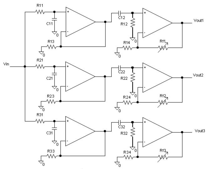
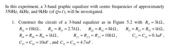
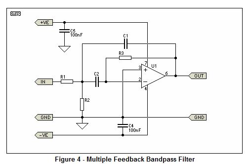
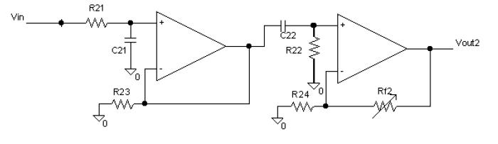
calculate bandpass filter
can anyone teach me how to calculate the centre frequency of this type filter??
i been searching all over for this kind of circuit but in vain..
i cant find a circuit that looks like this..
any kind people willing to show me the way?
thanks a lot![/img]
can anyone teach me how to calculate the centre frequency of this type filter??
i been searching all over for this kind of circuit but in vain..
i cant find a circuit that looks like this..
any kind people willing to show me the way?
thanks a lot![/img]