Continue to Site

Welcome to EDAboard.com

Welcome to our site! EDAboard.com is an international Electronics Discussion Forum focused on EDA software, circuits, schematics, books, theory, papers, asic, pld, 8051, DSP, Network, RF, Analog Design, PCB, Service Manuals... and a whole lot more! To participate you need to register. Registration is free. Click here to register now.

Using an opto-triac (MOC3020) to control a mains lamp

Status
Not open for further replies.
If the voltage between phases is 400V RMS it's peak will be 565V which is starting to get close to the triac rating, it would be advisable to use a higher voltage one. Don't forget that as well as the phase signal there will be noise and spikes from other equipment on the wires and these can increase the instantaneous voltage between phases.

If the voltage rating is OK, the triac should not turn on without one of two conditions being present: an appropriate voltage on the trigger or, a change in voltage faster than the triac can withstand. It is possible that noise is causing fast enough spikes to cause false triggering, especially with your inductive load. It would be a good idea to place a snubber network across the triac to minimize them.

Brian.
 

Re: opto triac

Hi,

I have connected 5V to MOC3021 in series with 470E resistor to limit the current through LED. Also i have used the same configuration at Output side of MOC. Instead of 180E, I have connected 390E/0.25W & Instead of 1.2Kohm connected 10K/2W. Also my load is at Cold side. That menas one phase of load is connected to Neutral & other end is connected to Triac terminal.

My resistor is getting burnt out. Software is fine. But facing problem with both the resistor. My load is simple 100W bulb. I was very surprised to see this problem. Please help me out.


----------------------------------------------------------------------------------------

Hello!

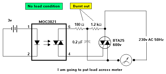
I am trying to switch AC motor through BTA25, I have opto-coupled it with MOC3021. I have a doubt, if the resistor of 180 ohms is sufficient to drive gate of BTA25.
In my case I have't put any load but tried to measure voltage across the output and common terminal. but both the resistors burnt. I have attached the schematics, the fashion in which I made connections.


HTML:
62_1263475367.gif


Normal link:
https://obrazki.elektroda.pl/62_1263475367.gif


Kindly help me out.
 
As bulb is not an inductive load, you may remove .2Mfd capacitor, and use 10K 0.5watt in place of the two resistors. ie in between Pin 6 of the MOC and pin of the Triac.
Cheers
 

The resistance values shown in the below schematic (180 ohm/1.2k) are the suggestions from a manufacturers data sheet for non-sensitive triacs (gate trigger curent 15 - 50 mA). It also suggests 2.4k for sensitive triacs. Resistor values around 10k aren't suitable in my opinion. They cause at least unnecessary high resistor losses and an unwanted delay in triac firing for each half-wave. Using a 10k resistor without a capacitor can result in not firing an unsensitive triac at all. This would actually burn the resistor.

The reported burned resistor cases with reasonable resistance values can be rather explained with defective triacs or wrong circuit connections. Similar circuits are working quite well in millions of instances world-wide, they can do for you, too.
 
  • Like
Reactions: snaiks

    snaiks

    Points: 2
    Helpful Answer Positive Rating
I have connected 3.3K in parallel with 10K. so now resistor effective value is around 2.7K. So in this case resistor should not get burned. Also resistors are getting heated.
I have check the connections, its absolutely fine. Also i have proper PCB for the same. THis is happening in 5 PCb's so even wrong triac can not be possible.

I got confused when resistors start burned. even i am surprised with such things. Any more suggestions ?


The resistance values shown in the below schematic (180 ohm/1.2k) are the suggestions from a manufacturers data sheet for non-sensitive triacs (gate trigger curent 15 - 50 mA). It also suggests 2.4k for sensitive triacs. Resistor values around 10k aren't suitable in my opinion. They cause at least unnecessary high resistor losses and an unwanted delay in triac firing for each half-wave. Using a 10k resistor without a capacitor can result in not firing an unsensitive triac at all. This would actually burn the resistor.

The reported burned resistor cases with reasonable resistance values can be rather explained with defective triacs or wrong circuit connections. Similar circuits are working quite well in millions of instances world-wide, they can do for you, too.


---------- Post added at 03:36 ---------- Previous post was at 03:10 ----------

Bulb is not an inductive load. That is true. But if i want to cater both Fan Speed Regulation & Bulb in one circuit then how can i do that.

If you have proper schematic, with proper resisotr/capacitor value with power rating then it will be good.


As bulb is not an inductive load, you may remove .2Mfd capacitor, and use 10K 0.5watt in place of the two resistors. ie in between Pin 6 of the MOC and pin of the Triac.
Cheers
 

Status
Not open for further replies.

Similar threads

Part and Inventory Search

Welcome to EDABoard.com

Sponsor

Back
Top