Continue to Site

Welcome to EDAboard.com

Welcome to our site! EDAboard.com is an international Electronics Discussion Forum focused on EDA software, circuits, schematics, books, theory, papers, asic, pld, 8051, DSP, Network, RF, Analog Design, PCB, Service Manuals... and a whole lot more! To participate you need to register. Registration is free. Click here to register now.

PURE SINE WAVE INVERTER using ir2110

Status
Not open for further replies.

jeffreywong

Junior Member level 1
Joined
Jul 14, 2009
Messages
15
Helped
5
Reputation
8
Reaction score
3
Trophy points
1,283
Location
north, kampar
Activity points
1,449
pure sine wave inverter

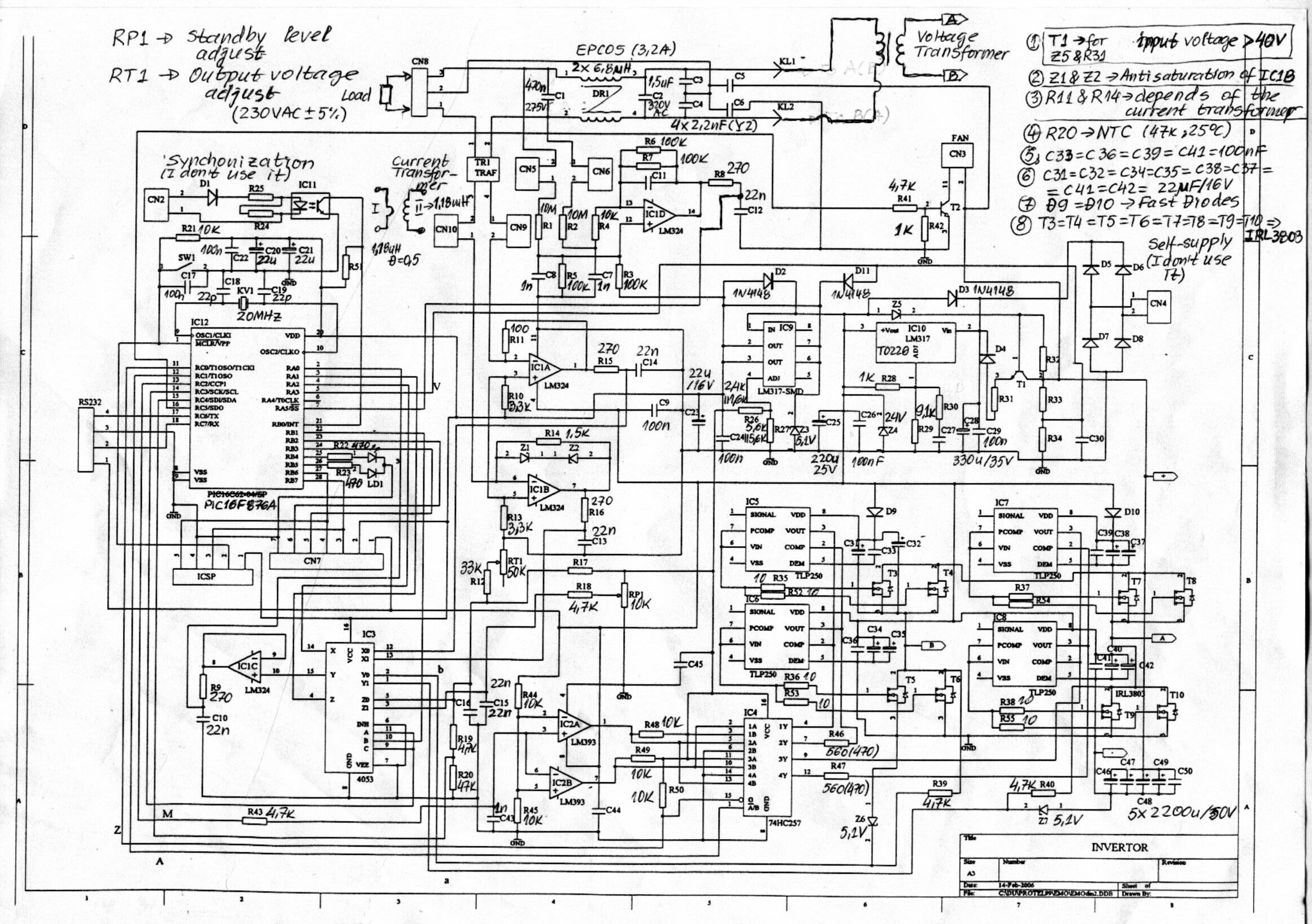
Im a student, im doing a project of Pure Sine Wave Inverter. I got the Pure Sine Wave Inverter from Internet, but the output is too small which is 120Vac from 12Vdc input.
1) Please give me some advice that how to modify it so that it give a output of 240Vac from 12Vdc ?
2) How you think about this circuit design?
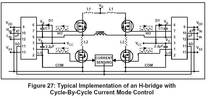
3)This circuit design have a Mosfet Driver component(IR2110), this make me very difficult to doing simulation because i have try many software, but all software lack of this component, please give me some suggestion what software should i use?
If you have better pure sine wave inverter design, please send to here or my email- jeffrey_5097@yahoo.com


Attact with circuit design diagram.


THanks for you advice.........

Added after 3 minutes:

sorry, i forgot to attact the circuit diagram, i will attact i here

the circuit design diagram is in


thanks.....
 

pure sine wave inverter circuit

Your circuit does not show any supply voltages.
On the other website you said the Mosfets have a +170VDC supply. 170V is the peak of 120VAC.

So if you want 240VAC output then feed the mosfets from +340VDC.
I don't know if your Mosfets will work from 340VDC.
 
pure sine wave inverters

try to simulate first with ideal components : ideal opamps, ideal switches, ... The working principle will not change when real components are used.

try to simulate ste by step the different parts in the design before doing a full circuit simulation. This will save you a lot of time, and will give you a good insight in the circuit working priciples.

Stefaan
 
Re: PURE SINE WAVE INVERTER

The problem is how can i get 340VDC from 12Vdc battery? By using transfomer, how can a transformer run in DC power?


Thanks...

Added after 3 minutes:

Can you show me the connection for DC-DC transformer schematic ?


Thanks...
 
PURE SINE WAVE INVERTER

The 12V powers a high frequency power oscillator that drives a small high frequency ferrite transformer. The high frequency high voltage output of the transformer is rectified and filtered which produces 340VDC that powers the PWM modulated Mosfets. The modulation is the 50Hz or 60Hz sine-wave that has the high frequency steps removed by an LC filter.
 
Re: PURE SINE WAVE INVERTER

For the last part which is 340DC feed to the H-bridge mosfet, and using PIC to generate PWM to control the switches. Can I use SG3526 instead of PIC to generate 50HZ PWM to control the switches? The current before the transformer is very high which is few teen ampere and after the ferrite transformer, it only few ampere, am I right?

Thanks...
 
Re: PURE SINE WAVE INVERTER

jeffreywong said:
For the last part which is 340DC feed to the H-bridge mosfet, and using PIC to generate PWM to control the switches. Can I use SG3526 instead of PIC to generate 50HZ PWM to control the switches?
Yes. Its reference voltage can be a 50Hz sine-wave.

The current before the transformer is very high which is few teen ampere and after the ferrite transformer, it only few ampere, am I right?
Yes.
 
Re: PURE SINE WAVE INVERTER

PIC16F627 + DAC0800 + RC Filter = pure sine wave then you need drivers to drive your power stage.:D
 
Now I want to know what if you dont use 340 VDC and instead run the H bridge stage with 12 VDC source.
Now to have working voltage of 220VAC, use a 12-220 VAC step up transformer at the output of the H bridge. Will the circuit still work. Guys your feedback would be appreciate.

Added after 5 minutes:

Now if I am correct in understanding the working of this circuit. One side of the H bridge is fed a PWM signal of high frequency and the other side is fed a 60/50Hz square wave signal. But if you see carefully both the driver IC have the same value for boothstrapping capacitor. I am in doubt as to whether the driver would properly turn the MOSFET ON due to insufficient gate voltage. :?::?:
 
EzEe1986 said:
Now if I am correct in understanding the working of this circuit. One side of the H bridge is fed a PWM signal of high frequency and the other side is fed a 60/50Hz square wave signal.
No, no, no.
Both sides of the H-bridge are fed the high frequency PWM signal. The PWM is modulated by a 50Hz/60Hz sine-wave, not a square-wave.
 
I understand what you are trying to say. But what i meant was the output can be controlled by only one side being fed the PWM signal and the corresponding high or low side transistor on the other side can be just keep On for the half cycle via a square plus.(since the output current would be controlled by the transistor being turned ON/OFF by the PWM signal). BTW I have verified the schematics working uptill the PWM generation in multisim as the driver IC model is not available in multisim and my theory was correct. This circuit does produces two different signals. A PWM signal for one side and 60 hz square wave signal for other half.

PWm signal is high frequency around 40 Khz and sq wave is 60 Hz.Though i understand its working alittle But i wanna know why.

Plus someone plz tell if you can just use a transformer at the output of H bridge to step up the voltage to desired 120 to 220 VAC or not.
 
The 50Hz or 60Hz is the sine-wave modulation of the width of the PWM pulses, not a square-wave.

You can use push-pull high current Mosfets to drive a center-tapped transformer that steps-up the voltage. Then an IR2110 is not used.
But usually a small high frequency DC to DC power supply makes a high DC voltage for the output Mosfets.
 

thanx for the reply

Audioguru said:
You can use push-pull high current Mosfets to drive a center-tapped transformer that steps-up the voltage. Then an IR2110 is not used.
But usually a small high frequency DC to DC power supply makes a high DC voltage for the output Mosfets.
In this case you dont use a H- bridge to do the switching rather a switching circuit output signal is fed to a combination of transistors in parallel to get high current gain. correct?

But I am interested in using a non CT transformer to stepup the output of H bridge. If you see it theoretically it is possible cause the output of the H bridge is approx 12 VAC and the MOSFET are capable of giving high current gain around 20 Amps. So say to have 0.5 A at the secodary of 12-220V transformer you will need around 15 A at the primary side. So for low output power can I use transformer at the output of H bridge.

Also would I need some kind of protection circuit?
 

Operating a 12V H-Bridge with a mains frequency transformer may be meaningful for low output powers, where the transformer size can be accepted but the effort for an additional DC/DC converter seems inappropriate. At 100 W, it's possibly reasonable, if you're not targetting to a miniature design.

Regarding PWM schemes, there are different options. The standard solution, as referred to by Audioguru, is feeding a PWM signal to both sides of the bridge. It has e.g. the advantage of distribute the switching losses evenly. In any case, it must use sychronous rather than on-off switching, otherwise, it can't handle reactive loads.
 

    V

    Points: 2
    Helpful Answer Positive Rating
Mosfets 15 years ago had a max current rating of only 20A. Today Mosfets have a much higher current ratings.

If you use a transformer to stepup the PWM signal then it will be a small ferrite high frequency transformer, not a huge and heavy mains transformer.
 
for the above schematic plz provide me the specs such as the wattage ,ac output voltage and dc input voltage .
 

so glad to discover this conversation. im currently working on my design of a pure sine inverter (12vdc-220vac). so far, what i already have is a working pwm signal generator and a schema of mosfet fullbridge using ir2110 as driver. my reference is the same with what jeffreywong posted. i have a friend who's also working on it but he's ahead of me. he told me that the mosfets are terribly heating up with ir2110 and the plan is replacing them with ir21834 (with adjustable deadtime). sadly, ir21834 is no longer available so we have to stick with ir2110. can you suggest any good ideas?

---------- Post added at 22:13 ---------- Previous post was at 22:10 ----------

and my plan is to use dc-dc step up converter to rise the input 12vdc into 350vdc before chopping it with the mosfet fullbridge. is that ok?
 

You may want to generate the deadtime in front of IR2110.
 

Well,i dont know what is making your mosfet heating up but what is the value of your boost trap capacitor,but i used IR2110 for my inverters and they work fine. .here is the diagram of the driver circute,dead time can be implemented by adding the resistor and diode in paraller before the gate of the mosfet.
 
Status
Not open for further replies.

Part and Inventory Search

Welcome to EDABoard.com

Sponsor

Back
Top