santom
Full Member level 2
input ip3
Hi all,
I would like to knoe why we are giving so much importance to the IP3 parameter even though the device is not experiencing that stage as per the normal theory.(It enters the saturation region once it attains the 1 dB compression point)
Could anyone tell me its importance in an amplifier's performance.Also I am attaching the respective Power Input Vs Power Output(Pin Vs Pout) schematic.Its the worst hand made diagram by me in the entire world though..:-D Pardon me for that..!!
Santom
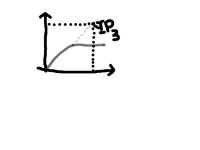
Hi all,
I would like to knoe why we are giving so much importance to the IP3 parameter even though the device is not experiencing that stage as per the normal theory.(It enters the saturation region once it attains the 1 dB compression point)
Could anyone tell me its importance in an amplifier's performance.Also I am attaching the respective Power Input Vs Power Output(Pin Vs Pout) schematic.Its the worst hand made diagram by me in the entire world though..:-D Pardon me for that..!!

Santom