Continue to Site

Welcome to EDAboard.com

Welcome to our site! EDAboard.com is an international Electronics Discussion Forum focused on EDA software, circuits, schematics, books, theory, papers, asic, pld, 8051, DSP, Network, RF, Analog Design, PCB, Service Manuals... and a whole lot more! To participate you need to register. Registration is free. Click here to register now.

Transistor Theory - need help with biasing the transistor

Status
Not open for further replies.

wbreslin951

Newbie level 6
Joined
Jan 11, 2009
Messages
11
Helped
0
Reputation
0
Reaction score
0
Trophy points
1,281
Activity points
1,378
bias a transistor theory

I'm doing my best to learn what I can so far, however I feel like I'm not getting very far. Here's what I've gotten so far:
Untitled.jpg


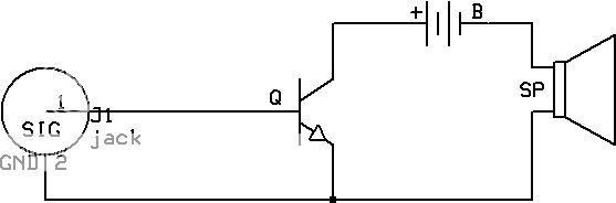
however, to me it seems completely incorrect, and if its correct in any sense, i know its missing alot of things, such as biasing the transistor, but thats all i know, and im not exactly sure how to do any of that. where do i go from here to design a working amplifier?
 

transistor theory in hindi

Speakers are designed to play AC to drive the cone back and forth.
Your transistor will drive the speaker with pulses of DC so the cone goes only in one direction.

If the speaker is 8 ohms and the battery is 9V then the peak current in the transistor and in the speaker is roughly 9V/8 ohms= 1.125A which is too high for a little battery, a little speaker and a little transistor.

With a collector current of 1.125A, the base current of the transistor should be 0.125A which is very high for a source to drive. An additional transistor must be used to drive this one.

Audio amplifiers are usually class-AB using a complementary pair of transistors driving the speaker through a coupling capacitor.

I have a sketch of a simple class-AB amplifier. The complimentary transistors usually have an emitter resistor and R2 is usually two diodes in series. Only a single input capacitor is used or a transistor is used to drive the circuit without an input capacitor. Usually negative feedback is used from the output to an input transistor. the output capacitor allows aC to feed the speaker and it blocks DC from going to the speaker.
 

transistor drive 8 ohm speaker simple

though i understood alot of what you've explained, i'm even more lost lol. how do you get the values for those capacitors? what about the resistors? and what is their purpose?. from what i understand, r1 is used to bias q1 and q2, but i dont know about r2 and r3. I could understand replacing r2 with two diodes to bias q2 using the current from r1, but still theres r3. about all i understand from this circuit is the purpose of the input and output caps, but i wouldn't know how to get those values.
 

transistor theory

The value of a capacitor is determined by the lowest frequency you want and the source and load resistance that the capacitor feeds.

The 470uF capacitor that feeds the 8 ohm speaker reduces the output power to half at the frequency of 43Hz.

I added a few parts to make a typical simple and cheap poor quality amplifier.
 

Status
Not open for further replies.

Part and Inventory Search

Welcome to EDABoard.com

Sponsor

Back
Top