jellybean
Junior Member level 1
rc transmitter circuit
Hi:
I would like some help on the circuits for an R/C toy that I am trying to modify from 27 MHz to 49 MHz operating frequency. I have re-engineered the transmitter and emitter circuits as best as I could. I have included all the circuits below. At first I thought these were Hartley oscillator-based FM transceivers, but my research on the Web has led me to believe that these are in fact an AM transmitter and super-regenerative type receiver. Now, I am not familiar wit this type of transmission so I need a little help.
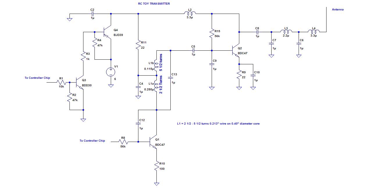
Let’s start with the transmitter circuit. This circuit runs off 4 AA cells in series to give 6V. This is an SMD board, so the only part values that I am certain of are the inductors and the resistors. The transistors show the actual markings on the parts and the packages are all SOT23 type. I am not 100 percent sure of the type (NPN, PNP, JFET, or BJT) but my in-circuit meter tests indicated NPN for all except Q4 (PNP). I tried all the online references, but still couldn’t cross them. I also tried the different combinations, and this is the circuit that made the most sense to me. Additionally, it appears similar to other reverse-engineered RC transmitters that I have seen on the Web. The capacitor values are default for the schematic program and not the actual values. I can’t remove and measure them because they are glued on (for wave soldering?). L1 &L5 represent a tapped tuning inductor with the measured value shown. C13 can be calculated from the operating frequency.
I would appreciate some feedback on the operation of the circuit. Actually, it’s only the Q2 circuit operation I am unsure of. I am assuming it’s the oscillator/amp. Q2 is an amp but might also serve as a feedback path to the oscillator. What is the role of C12? Feedback? Compensation? How about R11? Is it just for bias or part of a RC feedback network with C4? Or is C4 just filtering? Also not sure if the output filter is a pi or Tee filter. How would I optimally tune this circuit to 49 MHz. I would have to get a new inductor, because this one has been permanently set. I would also like suggestions for the capacitor value ranges.
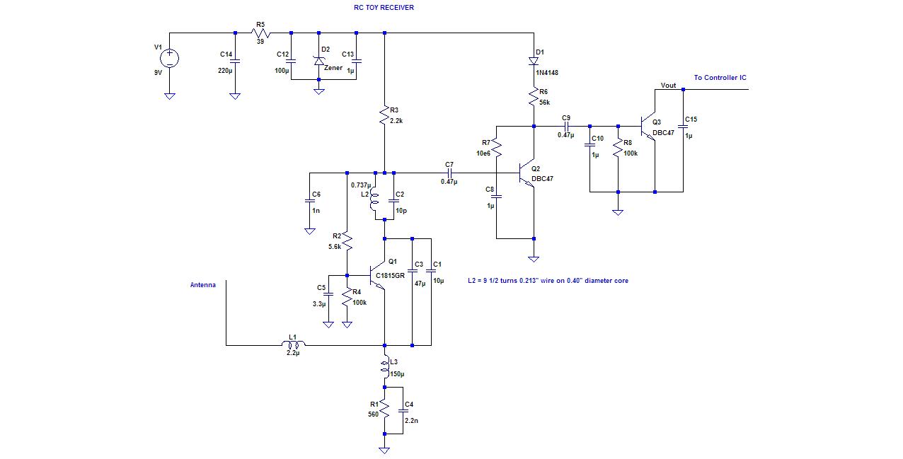
The transmitter is a little easier because it was mostly through-hole. The components and values in this schematic are the actual ones on the circuit except for the 1uF caps (C6, C8, C10, C13, & C15) and the zener diode (D2). Again, I would like some input on the operation of this circuit as a receiver/detector. I was expecting to see a diode detector somewhere if it was AM, and I am not sure how it would act as an FM detector.
On a final note, I have developed an interest in super-regen radio circuits and I would like to learn more about them in a more formal way. I would appreciate some feedback on texts or other references have formal discussions on their theory of operation. I don’t think that this is a part of modern electronic communication curricula any more. I have found a lot of material online, which I will use, but I would much prefer texts, etc. Thanks for your time.
Hi:
I would like some help on the circuits for an R/C toy that I am trying to modify from 27 MHz to 49 MHz operating frequency. I have re-engineered the transmitter and emitter circuits as best as I could. I have included all the circuits below. At first I thought these were Hartley oscillator-based FM transceivers, but my research on the Web has led me to believe that these are in fact an AM transmitter and super-regenerative type receiver. Now, I am not familiar wit this type of transmission so I need a little help.
Let’s start with the transmitter circuit. This circuit runs off 4 AA cells in series to give 6V. This is an SMD board, so the only part values that I am certain of are the inductors and the resistors. The transistors show the actual markings on the parts and the packages are all SOT23 type. I am not 100 percent sure of the type (NPN, PNP, JFET, or BJT) but my in-circuit meter tests indicated NPN for all except Q4 (PNP). I tried all the online references, but still couldn’t cross them. I also tried the different combinations, and this is the circuit that made the most sense to me. Additionally, it appears similar to other reverse-engineered RC transmitters that I have seen on the Web. The capacitor values are default for the schematic program and not the actual values. I can’t remove and measure them because they are glued on (for wave soldering?). L1 &L5 represent a tapped tuning inductor with the measured value shown. C13 can be calculated from the operating frequency.
I would appreciate some feedback on the operation of the circuit. Actually, it’s only the Q2 circuit operation I am unsure of. I am assuming it’s the oscillator/amp. Q2 is an amp but might also serve as a feedback path to the oscillator. What is the role of C12? Feedback? Compensation? How about R11? Is it just for bias or part of a RC feedback network with C4? Or is C4 just filtering? Also not sure if the output filter is a pi or Tee filter. How would I optimally tune this circuit to 49 MHz. I would have to get a new inductor, because this one has been permanently set. I would also like suggestions for the capacitor value ranges.
The transmitter is a little easier because it was mostly through-hole. The components and values in this schematic are the actual ones on the circuit except for the 1uF caps (C6, C8, C10, C13, & C15) and the zener diode (D2). Again, I would like some input on the operation of this circuit as a receiver/detector. I was expecting to see a diode detector somewhere if it was AM, and I am not sure how it would act as an FM detector.
On a final note, I have developed an interest in super-regen radio circuits and I would like to learn more about them in a more formal way. I would appreciate some feedback on texts or other references have formal discussions on their theory of operation. I don’t think that this is a part of modern electronic communication curricula any more. I have found a lot of material online, which I will use, but I would much prefer texts, etc. Thanks for your time.