Continue to Site

Welcome to EDAboard.com

Welcome to our site! EDAboard.com is an international Electronics Discussion Forum focused on EDA software, circuits, schematics, books, theory, papers, asic, pld, 8051, DSP, Network, RF, Analog Design, PCB, Service Manuals... and a whole lot more! To participate you need to register. Registration is free. Click here to register now.

transfer from the two inputs to one inputs of the Op Amp

Status
Not open for further replies.

bhl777

Full Member level 6
Joined
Sep 30, 2008
Messages
363
Helped
0
Reputation
0
Reaction score
0
Trophy points
1,296
Activity points
5,140
Hi guys, I have two questions about the transfering two inputs to one inputs of the Op Amp and I hope someone can help me a lot.
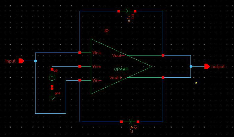
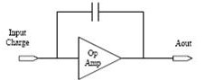
1.As the first attachment, the input is a charge and the output is the Voltage and its peak value is Q/C.Now I have a fully differential Op Amp and it has 2 inputs and 2 outputs, how can I connect the Op Amp to the capacitor?
91_1224296975.jpg

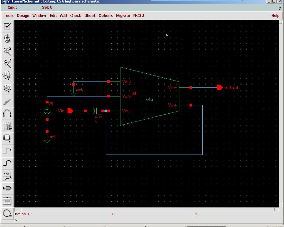
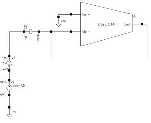
2.As the second attachment,this is a highpass Gm-C filter and the OTA has 2 inputs and 1 output. Now if we have an OTA with 2 inputs and 2 outputs(fully differential), how can I connect the two outputs in order to get the same effect?
51_1224297007.jpg

Thank you so much guys!
 

An inverting opamp without a series input resistor has an extremely low input impedance.
Its input is called a "virtual ground".
 

Audioguru said:
An inverting opamp without a series input resistor has an extremely low input impedance.
Its input is called a "virtual ground".
Hi man, thank you for your help. So you mean that if I use a fully differential op amp, I should connect both of the inputs to the ground as well as one terminal of the capacitor? And what is about the connection of the two outputs?
BTW, do you have the answer of my second question?

Thank you so much!
 

For the diagram no 1 why dont you try non inverting amplifier with unity gain.
Connect the capacitor between the ground and non inverting input and apply input to it. also connect a series resistor b/w ground and capacitor if you want to control the Charging time Q.
 

how can I connect the Op Amp to the capacitor
Depends on what you want to achieve. A fully differential charge amplifier simply has two feedback capacitors and a differential input.

how can I connect the two outputs in order to get the same effect?
Basically the same as above. You should have two high pass capacitors and a diffenrential source to use the fully differential OTA in a meaningful way.

You also can connect a single ended source to each circuit, grounding the respective other input and get a differential output signal as well.
 

FvM said:
how can I connect the Op Amp to the capacitor
Depends on what you want to achieve. A fully differential charge amplifier simply has two feedback capacitors and a differential input.


how can I connect the two outputs in order to get the same effect?
Basically the same as above. You should have two high pass capacitors and a diffenrential source to use the fully differential OTA in a meaningful way.
You also can connect a single ended source to each circuit, grounding the respective other input and get a differential output signal as well.

1.Hi man, what I want is to use the capacitor to change the input charge to a volatge whose peak value is Q/C. Could you have a look at the picture below? Am I right to do it?

2.I am still confused about the differential output because I am new to analog dsign, could you have a look at the pic below and point out if there is any problem in it? Thank you so much!
 

Read book **broken link removed**, it is free. You need to grasp basic concepts first.
 

The schematics are negatives that are very difficult to see.
The dots all over the place make it worse.

Added after 7 minutes:

Also the schematics were saved as fuzzy JPG file type instead of as a very clear GIF or PNG file type.

Here is the schematic made negative so it looks like a positive with a white background. The JPG fuzz cannot be removed and the dots all over the place are still on it.
 

Apart from the display colour problem, both circuits are completely wrong. I don't want to comment on this stuff further and basically aggree with Sinisas statement. Any text book dealing with fully differential amplifiers should show some meaningful circuits to my opinion.
 

Status
Not open for further replies.

Part and Inventory Search

Welcome to EDABoard.com

Sponsor

Back
Top