Continue to Site

Welcome to EDAboard.com

Welcome to our site! EDAboard.com is an international Electronics Discussion Forum focused on EDA software, circuits, schematics, books, theory, papers, asic, pld, 8051, DSP, Network, RF, Analog Design, PCB, Service Manuals... and a whole lot more! To participate you need to register. Registration is free. Click here to register now.

Calculating the base resistance of a transistor

Status
Not open for further replies.

simonwai999

Advanced Member level 4
Joined
Jun 30, 2008
Messages
114
Helped
0
Reputation
0
Reaction score
0
Trophy points
1,296
Activity points
2,175
Re: base resistance

hi, folks.
I would like to know why the resistor for the base of 2n3053 is 330 ohms
how do we calculater it ?
Here is what I think:

in a transistor
ic=ie
hfe = ic/ib
ib= ic/hfe
since ie approximately equals to ic
let ie be 300ma and hfe be 100
ib = ie( 300ma)/hfe( 100)=3ma

let's assume pin 1,2,3,4,5,,7 and 10 output of cd4017 = 3 volts

the resistance for the base of the transistor 2n3053 will be

R= 3/3mA
R=1000
we devide 1000 by 3 to let the transistor saturate
so the R for the transistor base is around 330 ohm

Am I correct?
When it comes to calculating the base of R of a transistor,
i am confused
Please correct me if i am right
thanks so much

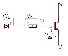
Added after 3 minutes:

here is the circuit
 

Re: base resistance

Well you are wrong with your calculation... Since you need to have BJ in saturation mode, well you cannot use hfe, because in saturation hfe<10. And it varies, so you cannot use it at all...
But there is another way.
In saturation you have
Vbes=Vbe=0.6V, usualy
Vces=0.2... You should check it in datasheet for transistor.
In that case you will get:
Ve=Vc-Vces,
Vb=Ve+Vbes
ib=(Vbb-Vb)/R

Where Vbes-saturation voltage on base-emitor
Vces-sat voltage on collector-emitor
Vc-collector voltage
Ve-emitor voltage
Vb-base voltage
Vbb-voltage on the other side of the base resistor.
ib-base current.

If you said that pins are on 3V, whitch i dont think is correct since that circuit is on 6V to 9V, but check it in data sheet, you get Vbb=3V-Vd, where Vd is a voltage on diode Vd=0.6V...
=>
ib=(3V-Vd-Vb)/R
=>
ib=(3V-Vd-Vc+Vces+Vbes)/R
That is from where you get your R, but if you can figure out ib...

Oh, and it just came to my mind, why do you think BJTs should be in saturation, and with 3V on pins it is not possible, since for saturation it must be that Vb>Vc.
Your Vc is on 6V to 9V, and pins on 3V... Therefore, it is not possible for BJT to be in saturation...
 

Re: base resistance

hi
thx for your reply
i read this site before i posted my question here

i realized this part i posted was wrong***
the resistance for the base of the transistor 2n3053 will be

R= 3/3mA
R=1000
we devide 1000 by 3 to let the transistor saturate
so the R for the transistor base is around 330 ohm ***

r should be the 4017 output minus 0.7/ ib
according to this site
**broken link removed**

in this site it stated something which is totally different from what you taught me
which made me more confused now

so when we have to calculate the r for the transistor base,
we need to know the output voltage of 4017 , the vces, the vd, the ib and.............
please show me how to calculate the 330 ohms in the circuit i posted here for i am getting more and more confused after reading this site once again

regards
 

Re: base resistance

Although hfe is advertised to be on the order of 100 for the 2N2222 or 2N3904, this current gain tends to drop significantly when Ic is large (i.e. when the transistor is conducting large collector current) or when the transistor is well within the saturation region. Thus, in calculating RB we will use hfe = 100, then to be certain we drive the transistor hard into saturation, we will reduce RB to 1/3 of the previously calculated value. To assure good isolation, however, we will not reduce RB below a value of 2.2kohm.
Quote from that site.

this current gain tends to drop significantly
He said it here and still used hfe=100... This is wrong. And reduceing Rb for 1/3 i dont know where did he get that, could be from his experience but i am not sure that is good also.

I chacked cd4017 and pins high output voltage is around Vcc, so in your case BJT cannot go to saturation, it can only be off, or in direct active mode.
25_1215870100.jpg


This is your circuit, if you see it is not the same as his, since you have collector attached directly to Vcc, and that means it cannot be in saturation, ever.
So your first calculation is OK, but you made one assumption:
let ie be 300ma

How do you know ie should be 300mA?


And, it could be that this whole circuit is wrong, since collector is on Vcc. It could be that 2n3053 should be replaced with some PNP transistor.
 

Re: base resistance

hi
thx for your detailed explanation
i will try to make this thing following this circuit to see if it would work
i will surely keep u posted

one more thing
if the transistor is something what we call emitter follower circuit
would the circuit still be wrong ?
Thanks
 

Re: base resistance

hi pal
anyway i will try to make this
give me some time since i am not always free
if it works or not
i am gonna try it
i will keep you posted
thanks for your help
regards
 

base resistance

Of course the transistor is an emitter-follower.
With a 9V supply, the output current of the CD4017 is about 11mA (from Texas Instruments datasheet) at 7V. If the LEDs are 2V red ones and the diode has a forward foltage drop of 0.7V and the base-emitter drop of the transistor is also 0.7V then the 330 ohm resistor has a voltage drop of 3.6VV and provides a base current of only 11mA. Therefore the total output current is about 220mA. A low gain transistor will have less output current and a high gain transistor will have more.

I think 10 LEDs are directly in parallel so they will unevenly share the current and will burn out one-at-a-time.
 

Re: base resistance

hi folks
today i hooked up a part of the circuit
power supply 9 v

and i connected 13 leds in parallel to one of the output pin of cd4017
directly
all 13 leds were lit properly
i used no resistors no transistors no diodes at all
i even ran it for hours
nothing wrong at all
the end of my report

regards
simonwai
 

base resistance

Wel, LEDs don't like to work in parallel without resistor. Because difference in V-I characteristic.
LEDs of the same type but a sightly different forward voltage at the specific current. LED whit the smaller forward voltage uses more current and it's brighter, that if one LED burns out, the remaining LED would use twice the current and then fail as well.
 

base resistance

The datasheet for the CD4017 from Texas Instruments has a graph showing its output current at various supply voltages and load voltages.
It has a typical output current of about 15mA into 2V LEDs with a 9V supply. 15mA is too low to destroy an LED. It was shared by the 13 LEDs so each LED had a current of only 1.2mA which is nearly nothing.

The output transistor of the CD4017 was dissipating 105mW which is slightly higher than its max allowed dissipation of 100mW. A current-limiting resistor would reduce the dissipation of the output transistor but it will also reduce the current.
 

Re: base resistance

hi
thanks for that info

i also know that theory
but
we do not connect like 10, 11 leds in parallel to the output of cd4017 ,
it is impossible to light up all ten or even eleven leds for one letter of the sign

regards
 

Status
Not open for further replies.

Part and Inventory Search

Welcome to EDABoard.com

Sponsor

Back
Top