Continue to Site

Welcome to EDAboard.com

Welcome to our site! EDAboard.com is an international Electronics Discussion Forum focused on EDA software, circuits, schematics, books, theory, papers, asic, pld, 8051, DSP, Network, RF, Analog Design, PCB, Service Manuals... and a whole lot more! To participate you need to register. Registration is free. Click here to register now.

Interfacing lm35 to pic microcontroller.

Status
Not open for further replies.

ronzam2002

Member level 5
Joined
Aug 20, 2007
Messages
81
Helped
2
Reputation
4
Reaction score
2
Trophy points
1,288
Location
san juan
Activity points
1,850
lm35 pic

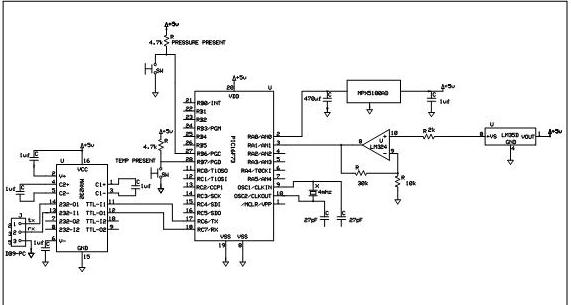
In figure below is the schematic of a smart sensor module. I want to know why do we need to connect the lm35(temperature sensor) to a operational amplifier to pic MCU? What is its operation? I also want to know the operation of the circuit of a mpx5100( pressure sensor) connected to the pic MCU.


lm35 calibration

33k/10k feed back = Amplification 3
Sorry 4 times

30k to 10 k
also buffering


From the data sheet
10 mV/Deg C from - 5 to 40
T Ambiant + 10 Deg C

I suppose that it means

-5 -> (10 -5) -> oupput 50 mV


40 -> (10 +40)
-> output -> 50 mv + (40-(-5)* 10) mV=500 mV

if it is amplified by 4 it will give a 2 Volts span ,from -5 to 40 deg C

If I am correct

gebe.:|
 

interfacing lm35 with pic

Output of LM35 is in the range of 10mV. This is too small for the controller to detect. So the signal is amplified using a OPAMP. Controller can detect any signal in the range of 100mv app and above.
LM35:
The LM35 series are precision integrated-circuit temperature sensors, whose output voltage is linearly proportional to the Celsius (Centigrade) temperature. The LM35 thus has an advantage over linear temperature sensors calibrated in
° Kelvin, as the user is not required to subtract a large constant voltage from its output to obtain convenient Centigrade scaling. The LM35 does not require any external calibration or trimming to provide typical accuracies of ±1⁄4°C at room temperature and ±3⁄4°C over a full −55 to +150°C temperature range. Low cost is assured by trimming and calibration at the wafer level. The LM35’s low output impedance, linear output, and precise inherent calibration make interfacing to readout or control circuitry especially easy. It can be used with single power supplies, or with plus and minus supplies .

The MPX5100/MPXV5100 series piezoresistive transducer is a state-ofthe-
art monolithic silicon pressure sensor designed for a wide range of applications,
but particularly those employing a microcontroller or microprocessor
with A/D inputs.
refer :
https://pdf1.alldatasheet.co.kr/datasheet - pdf/view/84243/MOTOROLA/MPX5100.html
 
lm35 amplifier

I've used an LM35 connected directly to a PICs A/D port. Works fine depending on the resolution you require. An accurate VRef+ will also help.
 

pic lm35

Sorry
I never tried this on PIC. I faced this problem long back with ATMEL controllers.But as per your thing even atmel should not have problem but i will re look into it.

But I am sure I had this problem.
 

lm35 microcontroller

I need a clear explanation of the ralationship between the lm35 and the amplifier to pic microntroller so that I can explain it clearly to write in my document...
 

lm35 with pic

If my original assesment of the data sheet is correct.Please correct me if I am wrong.
A device giving a low impedance output between :
50 millivolts ,starting at minus 5 degrees Centigrade
and
500 millivolts ,at 40 degrees centigrade
(increase of 10 millivolts with increase of ONE degree Centigrade)
AMPLIFIED by a factor of 4

MEANING: 500 millivolts multiplied by 4 = 2000 millivolts or in other words 2 volts

Finally the Pic Analog input will be supplied with a voltage depending of the temperature which the LM35 is subjected to

Namely 0.200 volts to 2 volts ,providing the temperature is between those limits.
The resolution will then be : 1.8/45=0.040 Volt per Degree Centigrade
I leave it to you to derive the formatting formula to derive the temperature in the program.


I honestly cannot explain any further...Nor better

May be someone else can...:?:.:D
 

lm35 operation

Hi,
Obviously, the function of the amplifier is to amplify the input signal and it is a common functional block of any data aquisition system. For the configuration shown, the amplifier gain is (1+Rf/R1) = 1+30/10 = 4.

The gain of the amplifier is chosen to ensure that the input signal range is brought up to about 80% of the reference value leaving a balance of 20% for over ranging purpose. In your case, therefore, if you are measuring temperature in the range of 0 to 100°C, then LM35 will give an output of 0 to 1000 mV. So, if you are using a reference of 5V, the maximum input signal will be amplified to 4V with a gain of 4 and you will be able to use a good range of your ADC thus.

This is the reason to use an amplifier in the front end.

Regards,
Laktronics
 

lm35 signal amplification

How about the operation of the mpx5100( pressure sensor). What is the responsiblility of the 2 capacitor on the corcuit of the pressure sensor? :|
 

connecting lm35 centigrade

Thank you(en passant)would have been very nice.:cry:
 

lm35+pic

Hi,
Regarding the capacitors, the one on the power supply line is again a standard power supply bypass capacitor ( typically a 4.7uF tantalum cap paralleled by a 0.1uF disc ceramic recommended for each analog and complex digital ICs) and the 470pf (not 470uf as appears from your diagram) on the signal output is a signal filter as recommended by the manufacturer, vide Freescale data sheet.

Regards,
Laktronics
 

lm35 amplifier circuit

So the 2 capacitor on the pressure circuit is used for filtering the pressure sensor when measuring pressure? :|
 

lm35 connected to an amplifier with the gain of 1

Hi,
Yes, the 1uF is to filter the power supply to the pressure sensor and the 470 pf is to filter the pressure signal output.

Regards,
Laktronics
 

lm35 pic circuit

i'm using this lm35dz. when i connect the lm35dz with 5V directly from USB (without any resistor), the lm35 will get very hot and smelly. why is this happend?

after that, i attach a 300 ohm resistor, 3.5V will drop on resistor and only 1.5V flow through lm35dz. can this lm35dz operate with this 1.5V?
 

lm35 mit pic

DViywa said:
i'm using this lm35dz. when i connect the lm35dz with 5V directly from USB (without any resistor), the lm35 will get very hot and smelly. why is this happend?

after that, i attach a 300 ohm resistor, 3.5V will drop on resistor and only 1.5V flow through lm35dz. can this lm35dz operate with this 1.5V?

Works fine at 5V you've connected it wrong.
 

pic lm35 circuit

blueroomelectronics said:
DViywa said:
i'm using this lm35dz. when i connect the lm35dz with 5V directly from USB (without any resistor), the lm35 will get very hot and smelly. why is this happend?

after that, i attach a 300 ohm resistor, 3.5V will drop on resistor and only 1.5V flow through lm35dz. can this lm35dz operate with this 1.5V?

Works fine at 5V you've connected it wrong.

hmm.. i connect to the correct pins. 5V to VCC, -5V to ground. output voltage from middle pin. the 5V is from USB supply with 100mA. but this make my lm35dz hot and smell like burn.
 

Status
Not open for further replies.

Similar threads

Part and Inventory Search

Welcome to EDABoard.com

Sponsor

Back
Top