Continue to Site

Welcome to EDAboard.com

Welcome to our site! EDAboard.com is an international Electronics Discussion Forum focused on EDA software, circuits, schematics, books, theory, papers, asic, pld, 8051, DSP, Network, RF, Analog Design, PCB, Service Manuals... and a whole lot more! To participate you need to register. Registration is free. Click here to register now.

Path Phase in free space

Status
Not open for further replies.

biff44

Advanced Member level 6
Joined
Dec 24, 2004
Messages
5,045
Helped
1,376
Reputation
2,748
Reaction score
1,055
Trophy points
1,393
Location
New England, USA
Activity points
37,896
Does anyone know how to even start figuring out the transmission path phase (and less importantly to me, the path loss) of this relatively simple structure? I have two monopoles with small circular ground planes. They are separated by a distance of around 3-5 meters. The two monopoles are not in the same orientation to each other, i.e. the one on the left hand side can be tilted/rotated to any direction, while the one on the right hand side stays fixed.

I have done some searches on the web, but have only come up with the most pedestrian of articles, usually only predicting the Eθ component.
I need something to take into accout the polarization mismatches.

Any ideas where to start? (p.s. I am not an antenna guy!)
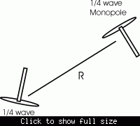


Added after 7 minutes:

Drawing is not to scale. And I am only interested in the far field.
 

I would start here: Warren L. Stutzman, Polarization in Electromagnetic Systems, Artech House, Inc., 1993.

The phase character of your antennas will be complicated further by the specifics of the feed and suppport.

This is not a trivial exercise but I would expect that it could be accomplished.
 

Polarization Mismatch Loss in dB between two Linear polarized antennas is = 20 log (cos φ)
where φ is the angle between antennas

For example the Polarization Loss between two monopole antennas (both in vertical position) is 0dB, and for two monopoles one vertical and one at 45˚ is 3dB.

To the Polarization Loss add the Free Space Path loss and find the total loss.
Free Space Path Loss(dB) = 27.6(dB) – 20*LOG[Frequency(MHz)] – 20*LOG[Distance(m)]
 

It is more complicated than that, unfortunately. After reading some papers, I concluded that the monopole should behave just like a dipole, since the ground plane acts as a "mirror" creating a mirror image of the monopole. And that a dipole has an electrical center right near where the two elements join the middle, since the dipole antenna must look like a dipole of two charges (+ and -).

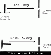
Then I actually performed this simple measurement below. I used a halfwave dipole at the receiving end, and a monopole at the transmitting end. I used a network analyzer and an RF amp to boost the signal level. Antennas were 3 meters apart, and tuned to 885 MHz. With the monopole vertical, I recorded path loss and phase and called them the references (i.e. 0 dB and 0 degrees). Then I rotated the monopole so that it was pointing toward the dipole, as shown below. I expected to see the signal null out (assuming it would be cross polarized), and assumed it would stay at roughly 0 degrees of phase shift. The data shows it does NOT null out, and the phase shift is huge! Not at all what I expected! So I guess I do not understand this phenomenon at all.


What really shocks me is the phase shift. If the monopole phase center was somewhere along the monopole whip, the longest it could be away from the rotating point would be 90 degrees. Yet During rotation I got 169 degrees! Seems physically impossible! The rotating point was chosen so the point where the whip joins the ground plane would remain 3 meters from the receiving antenna.

Oddly enough, there was a gain peak (+3.4 dB) with the elevation of the monopole at 45 degrees.

Some factors I have that might be influencing the data:
It is a small ground plane, ie around 1/2 wavelength in diameter
There might be some multipath, as it was not done in a proper anechoic chamber, and it is too snowy to do it outside this month.

Added after 24 minutes:

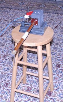
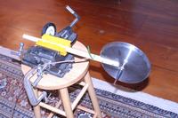
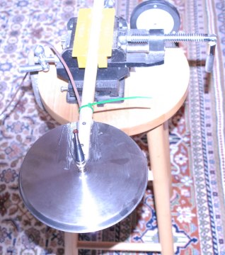
Here are what the antennas looked like:
5_1204636940.jpg


30_1204636996.jpg
 

Unfortunately I have to say (looking to your pictures) that you cannot get good antenna measurements in that chamber having on the floor a “Persian” carpet. Only if is a magic one, like that from “One Thousand and One Nights” :D
You need a real anechoic chamber, with cones also on the floor to minimize the reflections.

For monopoles using a finite-sized ground-plane of radius r, the pattern will tilt upward (from the ground-plane) and this tilt would vary inversely with r/λ ratio.
For imperfect ground-planes, the direction of peak directivity are at an angle above the horizon, and the current on the exterior of the element feed cable is nonzero because the feed cable is not completely shielded from the element fields. The current on the bottom surface of the ground plane at the feed cable is also nonzero.

You can modify the ground of the monopoles using λ/4-stub with an outer conductor shaped in the form of a conical skirt, as a result, this structure exhibits almost the same radiation characteristics of a vertical λ/2 Hertzian Dipole.
 

You could go outside and elevate the antennas so that they are well removed from the earth and get a better view of "free space". This is what a chamber is trying to replicate anyway.

Your monopole phase pattern will get very complicated (erratic?) as you approach the plane of the ground plane.

Fixturing is also an issue as I noted earlier ("The phase character of your antennas will be complicated further by the specifics of the feed and suppport. ")

Just what are you trying to accomplish? How good do the measurements have to be? Can you get by with simulations? Set the stage more fully and maybe we can be more helpful.
 

And I thought the persian rug would help! That room is a large one in a timber frame constuction house, with almost no metal nearby, so it is the best I can do. When the weather is better I do do most of my testing outdoors.

I was concerned about the cable ground currents, and did put some ferrite clamps on the outside of the cable, but it is still a valid concern. The quarterwave ground sleeve is a good idea that I can try.

What I am ultimately trying to do is to figure out the position of an object by measuring the rf phase shift between the object and a receiving antenna. So far I have figured out that a simple monopole works great when you rotate it in azimuth. But, as I rotate it in various elevation angles, weird things happen! For instance, when I point the monopole transmitter directly at the dipole receive antenna, as shown above, I expected a cross-polarized null, which I do NOT see in the measurements.

So I am trying to get an understanding of the radiaion pattern, especially the phase shift, as I move the transmit antenna in every possible direction/orientation. Obviously, actual measurements will differ from the theoretical predictions, but if I had good theoretical predictions, then I could at least start at a point where I could curve fit some data. I would like to be able to calibrate out the antenna orientation to perhaps +/- 2 degrees.
 

Okay, that means your room should be fine. Actually I got good antenna measurements in rooms like this, or wooden open sites.

As I said, you cannot get pattern measurements close to the theoretical predictions using a monopole without a proper ground. There would be unpredictable side lobes in the pattern, especially in the direction where you mentioned that should be a null.

Try a substitution method using calibrated dipoles, replace them with your monopoles and check for the phase change.
 

Systems using this idea have been built. I worked on one that used multiple baselines and monopoles on a large groundplane. Things worked well provided one stayed away from the plane of the groundplane and as you note things don't work well in the monopole null either.

See if you can find anything on TOAME (two object angle measurement system). It was fielded for Taiwan about 15 years ago and operated at about 2.4 GHz.

The magic was calming the phase response within the field of view (of interest).
 

Status
Not open for further replies.

Similar threads

Part and Inventory Search

Welcome to EDABoard.com

Sponsor

Back
Top