Continue to Site

Welcome to EDAboard.com

Welcome to our site! EDAboard.com is an international Electronics Discussion Forum focused on EDA software, circuits, schematics, books, theory, papers, asic, pld, 8051, DSP, Network, RF, Analog Design, PCB, Service Manuals... and a whole lot more! To participate you need to register. Registration is free. Click here to register now.

40MHz square signal through a lossy long cable. Need help

Status
Not open for further replies.

PaloAlto

Full Member level 4
Joined
Oct 8, 2007
Messages
194
Helped
35
Reputation
70
Reaction score
10
Trophy points
1,298
Location
Cádiz, Spain
Activity points
2,506
lossy cable

Hi all,

I need to transfer a 40MHz square wave through a lossy cable. The RLGC model of the cable is R=6.0ohm/m. L=243nH/m. G=1u. C=120pF/m. The max length is 5m. The signal itself is in fact not a digital signal. Instead is half cycle a reference value and the other half any data (so, it is an analog signal).

I've been working on it for a few days already. I am having problems with a very degraded signal and I am still not sure whether it is bad matching or just attenuation.

I have simulated the Zo of the cable over freq and the real part changes from 2.4K in LF to 45 ohm in HF. The imaginary part goes from 0 to 0, but in the middle frequencies it gets as high as 800.

I have a few fundamental questions:

* What is the bandwidth of a square signal? Does it have freq components below 20MHz? If so they would not be matched properly (?)
* Is the attenuation the same for the signal whether it is voltage or current?
* Is it possible to create a matching network for the entire frequency band. For instance, a 1rst order approach is a parallel R of 2.4K, then a series cap, and another parallel R of 45. But this doesn't match for the high X in mid freqs.

I would appreciate any help
Thanks
 

lossy cable db/m

Basically the said cable can achieve suitable results with resistive termination around 50 ohms at both ends. The main deviation is an additional attenuation due to cable resistance. But the simple lossy line model doesn't consider frequency dependant attenuation from skin effect, with real cable it would cause additional pulse shape distortions.

To my opinion, a more exact termination or possibly equalization circuit should be calculated based on a more exact cable model. A frequency dependant termination would be meaningful only, if reflections should be attenuated to an exceptional low level.

I don't understand, which kind of termination resulted in a very degraded signal.

Components below 20 MHz must exist obviously for a non-periodical signal, but I don't think that this changes a lot regarding termination.

Voltage and current drive would be equivalent, if the source termination is also adapted, series termination with voltage source and parallel termination with current source,
 

    PaloAlto

    Points: 2
    Helpful Answer Positive Rating
Re: 40MHz square signal through a lossy long cable. Need hel

I think you can try to place a 3-6dB attenuator designed for 45-50Ohms at the load followed by an amplifier to improve impedance matching, if the load impedance is not well defined.

For the old analog telephone coax lines they used manual/automatic equalizers, but those cables had at least a few km of length. For 5m the losses should be low, no need for an equalizer. You may choose a different cable, R=6 ohm/m seems quite high.

If the "reference value" is a DC voltage, you may use LPF/HPF and process different the signals.
 

Re: 40MHz square signal through a lossy long cable. Need hel

Thanks to both of you for taking the time to answer my questions.

FvM, could you clarify me a bit more some points, please?

... a more exact termination or possibly equalization circuit should be calculated based on a more exact cable model. A frequency dependant termination would be meaningful only, if reflections should be attenuated to an exceptional low level.

I do not know how to make such a frequency dependant termination. I need it to be purely resistive at low and high frequencies and conjugate for the imaginary part in the intermediate frequencies. Could you guide me or help me find the info, please?

I don't understand, which kind of termination resulted in a very degraded signal.

OK, I haven't explained myself very well here. I am trying to improve an application by re-designing the line driver and receiver. Right now, the transmission scheme is Vin -> CE + emitter resistance -> cable, (so, the transfer signal is current and the output is high impedance, not matched) --> common base (so, low-variable impedance, may be close to the desired 45 ohm) --> Rload converting it back to voltage, then gain stages, etc. As the frequency gets over a few MHz, the signal is attenuated (I guess, it could be reflexions too) and at 40MHz is useless.

Components below 20 MHz must exist obviously for a non-periodical signal, but I don't think that this changes a lot regarding termination.

Is it so? I thought that since the cable Zo is freq dependant and it's not matched for the intermediate frequencies, the mid-freq components would cause distortion in the signal.

Voltage and current drive would be equivalent...

OK, by know I think that indeed it doesn't matter whether is V or I, attenuation is the same. Moreover, I think that irrespective of matching, attenuation would be large. Is this so? Remember that as Eugen_E says, 6 ohm/m is really large, unfortunately it's impossible to change the cable. However, I have the impression that sending current is somehow more robust than V, am I right?

Thanks again to everyone for the help
 

Re: 40MHz square signal through a lossy long cable. Need hel

Hello,

i still don't think that frequency dependant termination or equilization is necessary, I share Eugen_E's viewpoint. The technique has been used e. g. for sampling oscilloscope delay lines with GHz bandwith requirements, utilizing passive RLC ladder networks. I still wonder, why the resistive component of your cable is that high. Is it at very thin or a "resistive" coaxial cable? In the first case, frequency dependant attenuation actually could be higher as usual and affect pulse response.

Empirical results for cable pulse response (without equilization):
https://www.slac.stanford.edu/cgi-wrap/getdoc/slac-tn-71-027.pdf

Mathematical method for equilization calculation:


From experience as well from a brief simulation, a 5 m cable should have a suitable pulse response with termination on both sides. Are your results from simulation or from real measurements? What is your requirement regarding pulse response in time and amlitude?

Regarding source driver. A current source with parallel load resistance would have probably a better behaviour abvove a few 100 MHz. It also implies a more simple circuit with discrete transistors. But a wideband amplifier with series termination could be used as well.

Regards,
Frank
 

Re: 40MHz square signal through a lossy long cable. Need hel

Yes, the cable is very thin, that's why the resistance/m is that high. The first time I saw the value, I thought they had made a mistake and they meant /km :roll:

It also looks unnecessary to me to do the (f) termination, the very high value of R makes me doubt. I will look at those papers, but I think that I first have to completely understand a few things. I'll put then at the bottom...

I have a very degraded signal from real measurements using the scheme described above. I also have sim results with matched i source and load that show what I believe is just attenuation, besides the 6dB attenuation, of course. The requirements were in principle 10 bits for a 1Vpp signal, however, I think that looking at the crappy results that the customer has right now, he'd be happy with just a decent level of signal. I need to sample the signal at the receiver, so, I would need something in the order of 3ns at least.

So, the main questions that I still have are:

With that RLCG cable, the degradation that I have, does it come from attenuation, or is it reflections? If it is the first, as I believe, then I cannot eliminate that no matter what, can I?

If I use voltage source, attenuation depends no cable length, is it the same for current source?

Many thanks again :D
 

Re: 40MHz square signal through a lossy long cable. Need hel

Hello,

10 bit accuracy is quite a lot, in this case, the cable properties should be analyzed more exactly. Basically, as I already mentioned, the simple lossy line model doesn't give sufficiant accuracy, cause it ignores skin effect which is essential for pulse shape distortions (and also the dominant factor for cable losses below 1 GHz). Can you give the exact cable type respectively the conductor dimensions and material? Alternatively an attenuation specification for e. g. 100 MHz could give a hint.

In addition to the 10 bit accuracy requirement, what's the effective acquisition window for your measurement, could be the time interval between pulse start and sampling, convoluted with a possible filter pulse response.

You also mentioned variable cable lengths. It's obvious, that pulse distortion and additional attenuation would vary with length. Only the -6dB attenuation for matched source and load termination is a constant.

Regards,
Frank
 

Re: 40MHz square signal through a lossy long cable. Need hel

Hi Frank,

You say that the RLGC model is too simple, which model would be better?

I actually have the cable with me. It is a AWG42. I am setting a testbench up to measure the Zo using a VNA. I'll let you know the info I as soon I get it.

In addition to the 10 bit accuracy requirement, what's the effective acquisition window for your measurement, could be the time interval between pulse start and sampling, convoluted with a possible filter pulse response.

I'm not sure I understand your question. The reference value is repeated every 25ns, so I have half cycle for the data 12.5ns. I need to sample that in the receiver, so the window should be at least something in the order of 2 or 3ns.

About the cable length thing, it's only that to me it's difficult to see that it's exactly the same with I and V. I always have the impression that with I the distortion is more controlled.
 

Re: 40MHz square signal through a lossy long cable. Need hel

Based on this paper:

**broken link removed**

an AWG42 cable would have a loss of about 8 dB/m. The cable is
extremely small, more apropiated for short distance between
modules inside a cell phone. Looks that 5 m is a long distance
for this cable.(40 dB losses). For other hand the diameter of the
cable will limit the maximum power handling of it.
 

    PaloAlto

    Points: 2
    Helpful Answer Positive Rating
Re: 40MHz square signal through a lossy long cable. Need hel

Hello,

I tried to estimate pulse distortion due to skin effect with the AWG42 microcoax cable. It's clear to me, that the frequency dependant losses cause significant pulse distortion, but I'm not yet sure about the quantitative results. PSpice is using fourier transform when terms like √s for the skin effect losses are introduced, which limits the accuracy of simulation. Basically I would like to use a different simulator for comparison.

It would be interesting to see the step response of the terminated cable over a longer time intervall, e.g. 100 ns to determine the 0.1% settling time, which would be a key parameter for the intended 10 Bit accuracy. I think, the pulse shape distortion could be compensated up to a residual error by applying a correction network designed in time domain.

Regards,
Frank

P.S.: I noticed, that some simulation tools have a model for lossy transmission line including skin effect, e. g. Aplac. They hopefully could give a correct estimation of pulse shape.

For the said 5 m AWG42 micro coax, a 0.1% settling can't be achieved within 12.5 ns without compensation or equalization. Transmission line termination should be set near to nominal 45 ohms to my opinion. Basically the termination should absorb reflections maximally, this is an optimization criterion different from pulse shape requirements in forward transmission.

Pulse shape compensation could be achieved either by analog means or in the digital domain by a FIR filter. If the data is sampled at 80 MS/s, as the problem suggests, 3 to 5 taps may allow a sufficiant compensation. As an important advantage, the coefficients could be directly calibrated from a step response measurement.

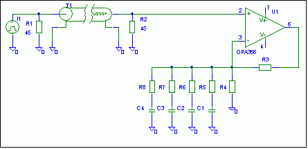
An analog compensation is possible by a ladder network, as shown in a principal circuit below. Similar circuits have been used e. g. in oscilloscope vertical amplifiers with delay line in former times:
49_1204610799.gif
 

    PaloAlto

    Points: 2
    Helpful Answer Positive Rating
Re: 40MHz square signal through a lossy long cable. Need hel

Hi jallem,

Thanks a lot for the paper, I'm still reading it, but it definitively looks like my beloved cable.

40db losses for 5m looks too much for me. I don't know which frequency you are talking about. For my working frequency could be something more in the order of 6db added to the 6db divider.

Frank,

I'm using spectre. The model is very similar to the spice one. It's called mtline and the RLGC data, as well as the length is entered. I also get frequency dependant losses that I believe correspond to real life measurements.

I've repeated the simulations with the cable terminated, (only on the receiver side) and the 0.1% error is reached after something like 3us.

In the end it will be something like the compensation scheme that you talk about...

I'll keep trying, thanks for your help :))

PS. I've attached the picture with the capture of the long time step response
 

Oh, by the way jallem,

Could you tell me how can I calculate the max power related to cable diameter, please?

Added after 2 hours 23 minutes:

The cable losses are 0.6dB/m, in total 3dB

That's 0.7 factor aprox
 

Re: 40MHz square signal through a lossy long cable. Need hel

Hello,

the 8 db/m spec is given in the qouted paper and is valid for 1 GHz. It doesn't matter much for you application. You can expect a √f proportional attenuation down to 10MHz, this would mean 2 db/m at 10 MHz and 5 db/m at 100 MHz.

A lossy cable model with L,C,R,G as parameters, without a conductor ρ and cable dimension does not give a correct simulation of frequency dependant attenuation or pulse distortion, cause it ignores skin effect, which is the dominant loss mechanism at higher frequencies.

Thus I think the shown simulation results are not corresponding to real cable behaviour. On the other hand, the long 3 us settling time isn't plausible to me, even considering reflections due to unterminated source, it may indicate additional simulation errors. I would suggest to compare with a real pulse measurement. Having the cable unterminated at the source is inappropriate to my opinion, cause reflections would be too high for 10 bit accuracy, even with a good termination matching at the receiver, which isn't possible exactly as you pointed out.

Regards,
Frank
 

    PaloAlto

    Points: 2
    Helpful Answer Positive Rating
Re: 40MHz square signal through a lossy long cable. Need hel

I think that probably by early next week I may have some measurement results, like the pulse response.

thanks again
 

Re: 40MHz square signal through a lossy long cable. Need hel

PaloAlto said:
Oh, by the way jallem,

Could you tell me how can I calculate the max power related to cable diameter, please?

Added after 2 hours 23 minutes:

The cable losses are 0.6dB/m, in total 3dB

That's 0.7 factor aprox
I would need to do a search in my library. But I can tell you now
that the maximum power handling depends on the ratio of the
radius of coaxial cable, the dielectric constant of the material
in between them and the maximum voltage the dielectric can
withstand before rupture.

The cable losses depend on the loss tangent of the dielectric,
the conductor losses and the skin depth(frequency).

I will try to get back to you on where to find the information.
 

Re: 40MHz square signal through a lossy long cable. Need hel

As a preliminary remark, the power handling shouldn't be an issue for a measurement application of the cable, I think.

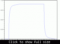
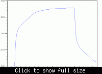
I was able to simulate the Fujikura microcoax with Aplac using the TLineDisp component, that models skin effect. I used the values from the Fujikura paper, except for the conductivity, that was reduced to achieve a 6 ohms DC resistance rather than 4 ohm the would result from 0.075 mm diameter. The pulse shapes are very similar to measurements I did several years ago, so I believe they are basically correct. It would be interesting to compare the results with real measurements.

This settling times (after subtracting the cable delay) could be determinded for the full terminated cable:

0.7 0.1
13.9 0.9
55.8 0.99
88.7 0.999


Bothside 45 ohms terminated case


Current source with 45 ohms load

I also append a description of the Aplac TLineDisp component used in the simulation.
 

Status
Not open for further replies.

Part and Inventory Search

Welcome to EDABoard.com

Sponsor

Back
Top