umery2k75
Advanced Member level 1
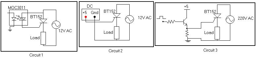
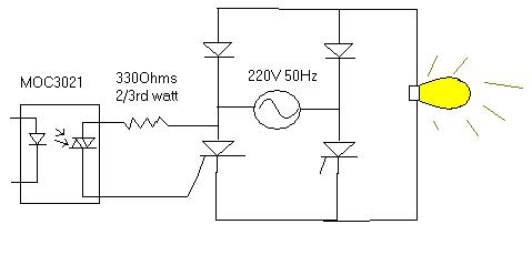
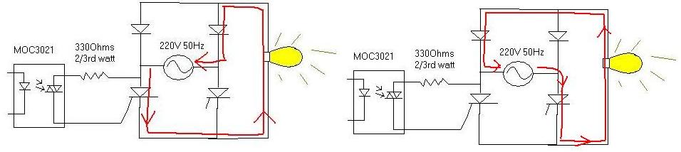
I checked the Circuit 1 and Circuit 2 and the SCR was working, inplace of LOAD, I had a small 12V torch bulb.Both of these circuits are working fine.
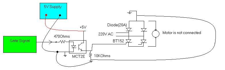
By looking at the way Circuit 1 and Circuit 2 are working, I am willing to make the Circuit 3, is this circuit ok.I'm using 2N2222 low power general purpose NPN transistor.I want to know is this good design(Circuit 3)?
I'm doubtful about Circuit 2 also, although it's working fine, maybe it only works fine in low voltage like 12V AC and will blow up in high voltage like 220V AC.I'm thinking about this, because when I see Cathode of SCR.I know it's just 0.7Volts lesser than the Anode.I measure 220V AC, so the peak voltage is 220*1.414=311.08V AC, this voltage will appear at anode and 311.08-0.7V = 310.38V AC will appear at the cathode.So now Power supply is Gnd is connected after the load and I know potential would have droped to 0V .Now when the AC supply changes it polarity maybe the higher potential voltage would than flow directly to the GND of power supply.Should I connect a diode in there, so as to block current flowing into it.This configuration worked fine at 12V AC Rms, but don't know what the consequences would be at 220VAC Rms.Actually all I want is to make a good triggering circuit for SCR.The load current is all about 20A, so the circuit 1 containing the MOC3011 will blow up at high current.