Continue to Site

Welcome to EDAboard.com

Welcome to our site! EDAboard.com is an international Electronics Discussion Forum focused on EDA software, circuits, schematics, books, theory, papers, asic, pld, 8051, DSP, Network, RF, Analog Design, PCB, Service Manuals... and a whole lot more! To participate you need to register. Registration is free. Click here to register now.

CB0703-PCB for "PICkit 2" DIY(Do It Yourself) fans

Status
Not open for further replies.
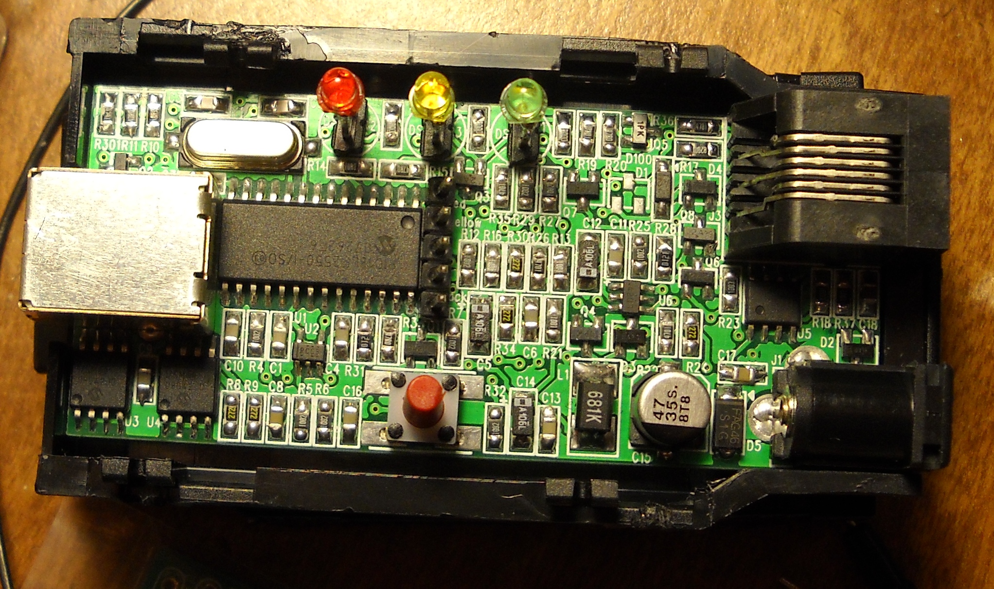
Re: pickit 2 open-source structure and clones

funnynypd said:
positive.
2550 doesn't have a 40 DIP package.
Many others also used the 4550 (by putting it in 2550 mode) based PK2. So it is doable from the document and practice point of view.

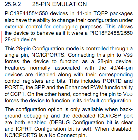
sorry..noob question funnynypd. how to put 4550 in 2550 mode?
thanks
 

    funnynypd

    Points: 2
    Helpful Answer Positive Rating
Re: CB0703-PCB for "PICkit 2" DIY(Do It Yourself)

funnynypd said:
Check it out, this is how DIY fans who only gets a 4550 and make a PK2:
93_1264697692.png
thanks funnynypd..the pin exist in plcc,but i have dip package, i can't find NC/ICPORTS pin in DIP package..can i just burn the .hex and good to go?
Sorry my english is terrible
thanks.
 

    funnynypd

    Points: 2
    Helpful Answer Positive Rating
Re: CB0703-PCB for "PICkit 2" DIY(Do It Yourself)

funnynypd said:
You should be able to give it a try. It won't damage anything assuming all external circuits are correct.
The 28 pin emulation just get rid of the extra hardware functions (inside the 4550), which a 2550 doesn't have.
Maybe someone actually tried in a DIP 4550 can give you more info.
i try some simulation on proteus with 4550,seems work ok..im still waiting for pcb from my pcb manufacturer. I will report here the result.
 

    funnynypd

    Points: 2
    Helpful Answer Positive Rating
Re: CB0703-PCB for "PICkit 2" DIY(Do It Yourself)

I assembled a BB0703 over the weekend and the programmer seams to be working fine. The software sees it and communicates but every time I try to program chip is says VPP voltage level error. I have tried breadboard. Ziff and with a 16f628A, 18F2331, 16F74 what is going on. I have gone through the diagnostics and troubleshooting with a volt meter. I am a newbee but Building PCB and assembly is my job. Thought I would start diving into this programming world and getting stuck.
Thank You
Eric
 

    funnynypd

    Points: 2
    Helpful Answer Positive Rating
Re: CB0703-PCB for "PICkit 2" DIY(Do It Yourself)

OK I think I found the problem just don't know how to fix it.
I went to the troubleshooting part when I get to step 2 Verify VPP I only get 9.2v and it fails. I am using a usb hub with a 6v 2amp power supply to make sure that there is enough power?
What could I do to resolve this.
I will try to post a pic of the build
Eric
 

    funnynypd

    Points: 2
    Helpful Answer Positive Rating
Re: CB0703-PCB for "PICkit 2" DIY(Do It Yourself)

WOW,
It seams sometimes I rush through..
Thank you for taking a look. Will make the corrections!
Will post the out come
Eric
I was wondering why the R301 was not listed in the kit. I thought you forgot about it
 

    funnynypd

    Points: 2
    Helpful Answer Positive Rating
Re: CB0703-PCB for "PICkit 2" DIY(Do It Yourself)

It looks to me now that I switched Q5 and Q8, Will change!

Added after 23 minutes:

NICE,
Thank you for all the help
Now time to do what I started out doing.

I will be back, I am sure with more struggles

Eric

0_1266414171.jpg
 

    funnynypd

    Points: 2
    Helpful Answer Positive Rating
Re: CB0703-PCB for "PICkit 2" DIY(Do It Yourself)

Yup,
Ran all tests and it passed, also PTG functioned properly
 

    funnynypd

    Points: 2
    Helpful Answer Positive Rating
Re: CB0703-PCB for "PICkit 2" DIY(Do It Yourself)

Oh thats great...
PicKit 2 -> PIC,AVR ...haha cost effective solution
 

    funnynypd

    Points: 2
    Helpful Answer Positive Rating
Re: CB0703-PCB for "PICkit 2" DIY(Do It Yourself)

I've ordered the BB0703+ 128 and intend to use it with MPLAB 8.5

I have a project that uses a 16F690 and I've designed in a 6 pin ICSP connector (only 5 used) that brings all the necessary pins out. I've been programming this on a PICstart+ clone and it works fine.

The Microchip web site says that I need an adapter and a cable...

PIC16F631*, 677*, 685*, 687*, 689*, 690*
- Use AC162061 ICD header & AC164110 adapter.

Do I really need these items?
 

    funnynypd

    Points: 2
    Helpful Answer Positive Rating
Re: CB0703-PCB for "PICkit 2" DIY(Do It Yourself)

Hi to everyone:

Hi, I'm new to the forum, I thank in advance for your help. First I apologize for my English, not the best.

I would tell them that I had an error and looking at this forum and others but none have found an answer or solution. I will describe the case where I am because I have seen in other posts some questions I guess I going to do, so I have already answered to get the help I receive routing.

I'm a programmer using the aoftware pickit2avrisp pickit2, I have SO Win7, I had no problems with the stationing of the programs (com0com, Microsoft Visual C + + 2008 Redistributable Package and avrstudio).

I tried it as directed on the page with the AvrStudio, CodeVision AVR AVRDUDE all programs recognize the programmer, with all of them I can recognize the signature of the avr's that I'm trying (atmega8 ATMEGA16) I can read and write to the fuses, I can read the flash but I can not program the flash, I get the following error:

Getting isp parameter .. SD = 0x03 .. OKOK
FLASH Reading input file .. OK
Entering programming mode .. OK!
Erasing device .. OK!
FLASH Programming .. OK!
Reading FLASH .. OK!
WARNING: FLASH byte address 0x0006 is 0xFF (should be 0x53) .. FAILED!
Leaving programming mode .. OK!

I changed the speed of the ISP Frequency AvrStudio both as Codevision AVR, but both have had the same problem, with AVRDUDE I get a similar message, not when written to the flash, but when the checks. I tried to ignore that message but when I test it in my circuit, it does not work and is not a problem because as I indicated fuses fuses if properly recorded.

UC I'm using new, so this is not the problem. I have attached some pictures so you can see the way I connected the atmega8 and messages that give me the AVRStudio, where people will see that the programmer avrstudio normally recognized as skt500. On the connection of atmega8 I tested with 10K resistors of 100 ohms, also making the SS pin to ground and also disconnected.

I hope I can help and sorry if I have dwelt much, what happens is that I wanted to be clear and answer some questions that someone in the forum I guess so.

Greetings and thank you again for your help
 

Another great help from you man..........!!!!!!!!
you are awesome!!!!!!!!!!
Regards,
Jerin. :)
 

Hey, I'm having some trouble with my PicKit2 clone, it kinda works but it has this problem. The VDD voltage levels are in reverse of how they should be. For example, if I go into troubleshooting section of the PicKit2 software, and I set 5v for VDD I get 3.9V , and if I set 4.5v I get 4.4V , The supposed VDD goes down but the real VDD goes up. In page 7 funnynypd asked someone to measure the inpup of the op-amp at 3.5v VDD ,that should be 1.8V , I get 2.8V. What could be the problem ? I should mention that I didn't use a pic18f2550 mcu but a pic18f4550 mcu, its the same chip but with some extra i/o pins .
 

good futuers, but impossible to be implemented at home by beginers in contrast to gtp programmer
 

Status
Not open for further replies.

Similar threads

Part and Inventory Search

Welcome to EDABoard.com

Sponsor

Back
Top