f1blop
Newbie level 1
hi everybody, thanks for reading my post, I hope somebody can help me with this issue.
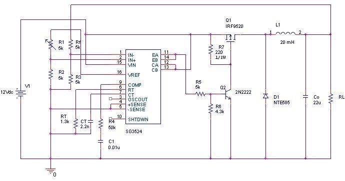
I'm making a basic 12V to 5V-0.5A-continuos mode-buck converter using SG3524 IC, P-Channel MOSFET, schottky diode, etc. When I test only the pwm and the mosfet it work fine, schitching at the right frequency, but when the rest of the ciruit is implemented and I try to measure the voltage in the diode I can't see the signal I'm expecting to see.
I don't know what's happening because at the output I'am having the right voltage (5V). It could be something related to the operation mode.
I'm forced to use a 20mH inductor.
Please help me