Continue to Site

Welcome to EDAboard.com

Welcome to our site! EDAboard.com is an international Electronics Discussion Forum focused on EDA software, circuits, schematics, books, theory, papers, asic, pld, 8051, DSP, Network, RF, Analog Design, PCB, Service Manuals... and a whole lot more! To participate you need to register. Registration is free. Click here to register now.

How to deal with the sweep of Kvco on PLL system design?

Status
Not open for further replies.

salem_eng1

Member level 2
Joined
Dec 7, 2006
Messages
43
Helped
8
Reputation
16
Reaction score
3
Trophy points
1,288
Location
Egypt
Activity points
1,606
Hi All

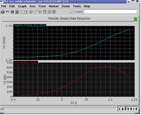
After I design my PLL with VCO gain Kvco=333.MHz/volts and design my system on that after I draw changing of Kvco with input voltage I found it change from Kvco(min)=60 MHz/volt to Kvco(max)=600 MHz/volts with non-Linear curve as shown in the figure.

1- Is this curve is OK or it is a bad design

2- How I can deal with the swep of Kvco on system design and its effect on stability, Lock time, Phase noise ,..........

Note:
Freq Vs Vcontrol in blue
Kvco Vs Vcontrol in red

61_1183584490_thumb.jpg


Thanx
regards
Salem
 

gain of vco

please could you tell me how to probe kvco curve by hspice
just like your fugure
thank~~~
 

hspice vco gain

in PLL project design, Kvco is not linear. sometimes it is OK, if the curve of Kvco is monotone.
In the considering of system stability, you should check when using the max Kvco and min Kvco, the PLL system should be both stable.

Ryan
 

    salem_eng1

    Points: 2
    Helpful Answer Positive Rating
what do you mean by vco has a linear tuning curve

Hi,Salem:

First of all,I think there is no problem of your simulated result.

But, in practice,Kvcomax:Kvcomin=10:1 is definitly not a good choice.It will cause the PLL bandwith to vary 10x.What is more,If you run full process corner simulation,the Kvcomax:Kvcomin will be even worse.

I think you should make your VCO run at the middle part of your F-V curve,this will reduce Kvcomax:Kvcomin to less than 2:1,which is a better choice.If the frequency range is not covered, you can use more VCO bands.

Remember:The linearer of KVCO,the easier the system design.

Best wishes!
 

    salem_eng1

    Points: 2
    Helpful Answer Positive Rating
how to compute vco gain

lineage050505 said:
please could you tell me how to probe kvco curve by hspice
just like your fugure
thank~~~

I don't make it using hspice. Unfortunately I don't have any idea about it.
I used the Specter simulator under cadence tools.

I plot this curve using the pss simulator you can read more about it in the documentation manuals of cadence.

I Hope that help you
 

kvco curve

lineage050505,

you can use .measure statement in Hspice to measure the period and then the frequency of the VCO after .tran simulation.

Best regards!

chenmy
 

vco gain measure hspice

what type vco you used?
 

pll hspice kvco

It seems that the VCO gain is not low, and the linearity is not very good. This is not good for PLL system, and also the phase noise performance will not easy to control.
 

    salem_eng1

    Points: 2
    Helpful Answer Positive Rating
constant kvco

What you can do is to use discrete VCO tuning together with your continuous tuning. In this case you won't have to sweep the whole KVCO curve, instead you will have sub-bands each with linear acceptable KVCO variation. The drawback is that you will need another loop to control the discrete part of your VCO (A frequency counter can do the job)
 

    salem_eng1

    Points: 2
    Helpful Answer Positive Rating
vco corner simulation

How to control the LC vco gain?
if we can control it, we can linearize it?
so, what are affecting parameters of Kvco?

thanx in advance
MohamedAbouzied
 

reduce vco gain

I think the Kvco is affected mainly by the efficiency of your varactor. If the capacitance of the varactor linearly changes with the applied volt, This will make your vco more linear. Also decreasing your frequency range makes the vco more linear.

The most important thing here I want to ask to you is that how linear you want your vco. I mean what is range of your Kvco variation your system required. As you know you will not get a constant Kvco this is an ideal case. All you want is a Kvco with an acceptable range which will not affect your system loop stability, Loop frequency, phase margin and the lock time.

As an example of the above curve the Kvco change from 60MHz/volt to 600MHz/Volt. So you have to go back to your system and simulate it on the value of 60MHz/volt and also the value of 600MHz/volt if your system works well in both cases and satisfy the required specs that mean in between this 2 values the system is OK and this range of Kvco is acceptable and if not you have to go back and either change your system parameters by doing some changes in the loop filter or back to your vco and try to change its Kvco linearity.

Another approach you may use to make the KVCO constant is to make a VCO with multiple varactors each one with the same KVCO and a small range to make it linear. In this case you need a control circuit to control which range(varactor) to use. It may be a frequency counter like "mbyoussef"suggest or any other approach you may think about.

Best Regrds,
Salem
 

Status
Not open for further replies.

Part and Inventory Search

Welcome to EDABoard.com

Sponsor

Back
Top