SanjKrish
Member level 3
I have two resistances which I will call them as loads... and they are purely resistive...
First one is a heavy load( A geyser which has 1000Ω resistance coils to heat up the flowing water)
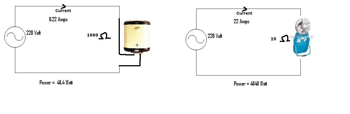
Second is a very light load( A hand held electric fan of 10Ω )
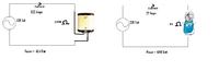
Intuition says the geyser should be consuming more power as it is a heavy load..:idea::idea:
but calculation shows it otherwise...:shock::shock::shock:
Help me understand:?::?:
First one is a heavy load( A geyser which has 1000Ω resistance coils to heat up the flowing water)
Second is a very light load( A hand held electric fan of 10Ω )
Intuition says the geyser should be consuming more power as it is a heavy load..:idea::idea:
but calculation shows it otherwise...:shock::shock::shock:
Help me understand:?::?: