Continue to Site

Welcome to EDAboard.com

Welcome to our site! EDAboard.com is an international Electronics Discussion Forum focused on EDA software, circuits, schematics, books, theory, papers, asic, pld, 8051, DSP, Network, RF, Analog Design, PCB, Service Manuals... and a whole lot more! To participate you need to register. Registration is free. Click here to register now.

555 monostable pulse width modulator

Status
Not open for further replies.

boylesg

Advanced Member level 4
Joined
Jul 15, 2012
Messages
1,023
Helped
5
Reputation
10
Reaction score
6
Trophy points
1,318
Location
Epping, Victoria, Australia
Activity points
11,697
In the 555 datasheet they have a pulse width modulation circuit similar to this with the only difference being that they have pin 5 labelled as 'audio signal in'.

What are you supposed to do with pin 2? Leave it unconnected?
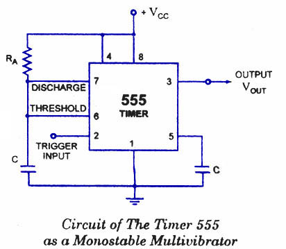
555-monostable-multivibrator.jpg
 

What are you supposed to do with pin 2? Leave it unconnected?
No, pin 2 is the input. This isn't an astable multivibrator, or oscillator. It requires input pulses.
 

No, pin 2 is the input. This isn't an astable multivibrator, or oscillator. It requires input pulses.

So we need to input a carrier wave through pin 2 and then an audio signal through pin 5?

So you would need an astable multivibrator AND this circuit then? Plus what ever you need to generate the auido signal.

With such an arrangement would the audio out signal seem as though it has passed through a narrow band filter as is the case when you pass an audio signal into pin 5 of an astable multivibrator?
 

So you would need an astable multivibrator AND this circuit then? Plus what ever you need to generate the auido signal.
Yes. You could save a bit of money and PCB space by using a 556 - it's like two 555s in one chip.

With such an arrangement would the audio out signal seem as though it has passed through a narrow band filter as is the case when you pass an audio signal into pin 5 of an astable multivibrator?
I don't see why the output should seem filtered using either approach, as long as the astable frequency is high enough.

The advantage of doing it this way is that the frequency will be constant, only the pulse width will be changed by the audio.
 

Yes. You could save a bit of money and PCB space by using a 556 - it's like two 555s in one chip.


I don't see why the output should seem filtered using either approach, as long as the astable frequency is high enough.

The advantage of doing it this way is that the frequency will be constant, only the pulse width will be changed by the audio.

I forget who it was now, but one of you guys suggested that audio modulating an astable mulitvibrator is like passing the audio signal through a narrow band filter and I assume that is why the sound coming out of my flyback based plasma speaker seems a bit 'tinny'.
 

That's just the nature of plasma speakers: they can make good tweeters but they can't produce bass or even much midrange - they just can't move enough air for that.

If you could listen directly to the output of the 555, it shouldn't sound "tinny", although it may be a bit distorted.
 

I think the 'tinny' reference was mine.

To change the mark/space (on/off) RATIO of the output you have to change the relative rates at which the capacitor on pin 6 charges and discharges. The schematic shown is clearly labelled "monostable" which means it has one stable state and applying a pulse to it's input (pin 2) makes it switch state until the capacitor has charged then it reverts back to the stable off state again and stays there until re-triggered. The circuit is to create constant length output pulses regardless of how long the input pulse lasts.

To make it oscillate, it has to be wired in "astable" mode (not stable) where the current output state changes repeatedly as the capacitor charges and discharges.

Pin 5 is not an audio input, it controls the current to the charge and discharge circuit which in astable mode makes the capacitor charge and discharge at different speeds and hence produce different frequencies. As I explained in an earlier thread, to get different volumes from your plasma you have to change the voltage (and therefore plasma temperature and air wave compression) but by feeding audio to pin 5 you change the frequency not the voltage. In fact the voltage will remain fairly constant and the only reason you hear sound from the plasma is because the circuit efficiency changes slightly as the frequency is varied.

I think what you are trying to achieve is linear PWM which is very difficult to get from a 555, especially over wide pulse width range. The classic way to make PWM is to use an oscillator (a 555 if you like) to generate a triange shaped wave then feed it and the audio into a comparator. The comparator will switch state when one exceeds the voltage of the other and the pulse width will vary acording to how far 'up' the triangle the two meet.

Brian.

Is this sort of arrangment any better Brian:

Where you feed audio into pin 5 and a signal from an astable multivibrator into the trigger pin.

It has been suggested that this arranegment does not vary the frequency, only the pulse width.

**broken link removed**
 

Much better - but this is basically what the original monostable schematic showed. You have to provide a fixed frequency to the trigger input from another oscillator and it has to be at the frequency of your arc generator and in any case several times higher than the highest audio frequency you intend to use. The RC network has to set the pulse width in conjunction with the voltage on pin 5. I would suggest setting a fixed voltage on pin 5 of about 60% of the supply voltage so it is central in its operating range and then select R and C for about 50% duty cycle. You will not get a great PWM range and it won't be very linear, the 555 isn't intended to be used for audio purposes!

Brian.

Well good enough then. I am not trying to make a high fidelity amplifier here after all.

I am intending to try audio mudulating a tesla coil next. So the PWM audio signal will be fed into the enable pin of the mosfet gate driver IC.

I am presuming that is how they do it on the youtube videos of musical tesla coils.

Will get the tesla coil working in its basic configuation first.

To save having 2 x 555s running off two seperate power supplies, so that the astable 555 output is 60% of the voltage supply for the monostable 555, I could just pass the astable output through an appropriate voltage divider. The 555 trigger pin is also fairly high impedance anyway isn't it?

I have already setup twin astable 555s at 50% duty cycle and with changeable timing capacitors. All I have to do is setup another board with twin monstable 555s with the output of these going to my dual inverting/non inverting mosfet gate driver IC (with the enable pins) Have ordered these along with the hex inverter chips for the antenna setup.

Another board will contain the antenna related circuitry and I will just link all these together via terminal blocks.

When it was said to connect a neon tube in parallel with the antenna to protect it from HV strikes, I am now assuming they meant those little glass bulbs that you sometimes find on TV circuit boards. Neon tubes have negative resistance characteristics when conducting I believe so it provides a preferential very low impedance for the HV when they start conduncting at 90V?

- - - Updated - - -

Much better - but this is basically what the original monostable schematic showed. You have to provide a fixed frequency to the trigger input from another oscillator and it has to be at the frequency of your arc generator and in any case several times higher than the highest audio frequency you intend to use. The RC network has to set the pulse width in conjunction with the voltage on pin 5. I would suggest setting a fixed voltage on pin 5 of about 60% of the supply voltage so it is central in its operating range and then select R and C for about 50% duty cycle. You will not get a great PWM range and it won't be very linear, the 555 isn't intended to be used for audio purposes!

Brian.

What would you recommend as the pulse width/duration on the monostable 555?
 
Last edited:

Status
Not open for further replies.

Part and Inventory Search

Welcome to EDABoard.com

Sponsor

Back
Top