Continue to Site

Welcome to EDAboard.com

Welcome to our site! EDAboard.com is an international Electronics Discussion Forum focused on EDA software, circuits, schematics, books, theory, papers, asic, pld, 8051, DSP, Network, RF, Analog Design, PCB, Service Manuals... and a whole lot more! To participate you need to register. Registration is free. Click here to register now.

555 square wave generator

Status
Not open for further replies.

Milutiche

Newbie level 4
Joined
May 25, 2012
Messages
6
Helped
0
Reputation
0
Reaction score
0
Trophy points
1,281
Location
Whangarei - New Zealand
Activity points
1,326
Hello, Please help me, I have designed a very basic square wave generator to run a speedometer circuit board which is providing output to control a stepper motor

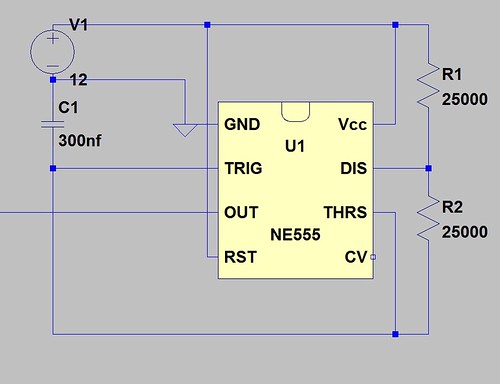
Square Wave by Jason Milich, on Flickr

R1 and R1 are replaced with a double 100k pot, when I adjust the pot the frequency changes, my problem is, when I look at the signal on a scope it doesn't appear that the wave pulls right down to ground, I can use my soundcard and output a signal that works just fine.

ARGHHHHH!

alternatively, any tips on designing a cheap 4 wire stepper motor variable speed controller
 

Some simple stepper motor controllers:

http://www.eleccircuit.com/basic-stepper-motor-driver-by-74194/

**broken link removed**


stepper2.gif


http://www.techlib.com/electronics/stepper.html

http://www.circuitstoday.com/stepper-motor-controller


**broken link removed**
http://www.eleccircuit.com/4013-and-irf510-easy-drive-a-stepper-motor/


100994_2lo.jpg


bipolar_stepperP2.gif


more details here:

http://www.theremin.us/Circuit_Library/bioplar_stepper_motor.htm
 
Last edited:
R1 and R1 are replaced with a double 100k pot, when I adjust the pot the frequency changes, my problem is, when I look at the signal on a scope it doesn't appear that the wave pulls right down to ground, I can use my soundcard and output a signal that works just fine.
How low is low enough for your application? The datasheet indicates that when the output of a 555 is lightly loaded, it should swing down to 0.01V or less in the low state, and to about 0.1V at 10mA load.
 

Hey thanks for the help,
pjdd, It looked to be sitting at about 0.4v on my scope, I did manage to work my way around this problem by connecting the output of my square wave generator directly to the IC driving the stepper motor. so far all is good. :)

---------- Post added at 20:02 ---------- Previous post was at 19:56 ----------

Hey thanks for the help,
pjdd, It looked to be sitting at about 0.4v on my scope, I did manage to work my way around this problem by connecting the output of my square wave generator directly to the IC driving the stepper motor. so far all is good. :)
 

would it be easy to reverse the stepper motor using this circuit? I've come across a bunch of 6 wire steppers that might be more suitable for my application

https://www.eleccircuit.com/4013-and-irf510-easy-drive-a-stepper-motor/

Cheers

EDIT: another question, I just ran a six wire unipolar stepper motor with my four wire driver ( not connecting the center wires for each coil) can I just connect the center wire to my supply voltage? and if so will this give me more torque?
 
Last edited:

I think there is a mistake in that drawing. Each diode should be connected between the MOSFET drain and +12V. (Only D2 is drawn correctly).

The reason for the diodes is because the load is inductive. Without the diode, when the MOSFET switches off, the voltage on the drain will tend to shoot up briefly to a high voltage, which could damage it.
 
Last edited:

Status
Not open for further replies.

Similar threads

Part and Inventory Search

Welcome to EDABoard.com

Sponsor

Back
Top