Continue to Site

Welcome to EDAboard.com

Welcome to our site! EDAboard.com is an international Electronics Discussion Forum focused on EDA software, circuits, schematics, books, theory, papers, asic, pld, 8051, DSP, Network, RF, Analog Design, PCB, Service Manuals... and a whole lot more! To participate you need to register. Registration is free. Click here to register now.

[SOLVED] [moved] BLDC driver timining is totally wack, what's the reason?

Status
Not open for further replies.

righteous

Full Member level 2
Joined
Nov 29, 2017
Messages
130
Helped
0
Reputation
0
Reaction score
0
Trophy points
16
Activity points
1,282
Gents,

Getting back to my running BLDC, I looked at the timing of the hi and low drivers, it is amazing that thing is spinning around the way the signals are out of alignment, so I would like to get the timing in order so that it may run top efficient.

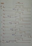
This is the hand made timing diagram of the hi and low of the three half bridges:
IMG_20180405_210718.jpg

I notice that the B-hi and B-low are both 1.5ms in duration, whereas A and C are both 1.1ms, so why the h... is that? Is that a misalignment of one hall sensor?

Otherwise ABC-low signals are all over the place, I can't see any pattern in it that would give a hint to what the problem might be.

The controller is implemented with a PIC 16F1933 and the code is adapted from AN857 Brushless DC Motor Control Made Easy (yeah right ...'easy'... however the free running Timer0 is a masterpiece, but annoying - I would prefer to do it with interrupts, but I need to get the timing right first)
 

Come to think of it, maybe this is more suitable for the microcontroller department? It doesn't seem to be a peripheral hardware issue as the timing signals are written to the port all at the same time (one byte)? So where can I request this thread to be moved to the microcontroller department?
 

Hi,

I´ve moved the thread.

****

To verify the problem you should include the halll signals into your diagram. With the exact timing relation to the power bridge control signals.
I assume the brige signals are symmetric with 120° phase shift.

But maybe the hall signals are distorted by the power signals. This may lead to wrong readings at the microcontroller input and thus it may lead to wrong microcontroller output signals.

Klaus
 

I assume the brige signals are symmetric with 120° phase shift.
Klaus

Yes, it's this setup:
IMG_20180319_121640.jpg
And the driver stage schematic is here: View attachment bldc-driver.pdf


To verify the problem you should include the halll signals into your diagram. With the exact timing relation to the power bridge control signals.

I would need a logic analyzer for that, but here's a scope shot of the hall signals at the input pins of the MCU
SDS00014.PNG
ch1: A
ch2: B
ch3: C

But maybe the hall signals are distorted by the power signals. This may lead to wrong readings at the microcontroller input and thus it may lead to wrong microcontroller output signals.
Klaus

It doesn't seem so, but they look a bit "off" timing wise to me, though the signals are clear enough and don't change in relation to each other.
 

Hi,

Klaus:
I assume the brige signals are symmetric with 120° phase shift.

righteous:
Yes, it's this setup:
That´s how it should be, but your scope picture shows smething different.
BLDC_Hall_timing.PNG

The timing is awful. Cheap motor? If you can´t adjust the hall signals, then you can´t expect higher quality signal output from microcontroller unless you put a lot of effort in the software.
All the signals should be 50% duty cycle. And 120° phase shifted.
******
righteous:
I would need a logic analyzer for that, but here's a scope shot of the hall signals at the input pins of the MCU
No, you don´t need a logic analyzer to add some signals to your hand drawn diagram.
For timing alignment you just need to refer to the timing of one signal that already is in your diagram.
A two channel scope is sufficient. For sure a 4 channel one is better.

Klaus
 

The timing is awful. Cheap motor? If you can´t adjust the hall signals, then you can´t expect higher quality signal output from microcontroller unless you put a lot of effort in the software.
All the signals should be 50% duty cycle. And 120° phase shifted.

No, quality-ish motor without sensors. So I had to glue 3 hall sensors in place, but when the epoxy had set, I noticed one sensor was 1-2% misaligned, but that shouldn't cause such a big difference.

I have attached the code at the bottom.

How many green lines is 120° in your annotated scope shot?

For timing alignment you just need to refer to the timing of one signal that already is in your diagram.

Duly noted, I will do so.
 

Attachments

  • control5.asm.txt
    6.8 KB · Views: 64

Hi,

How many green lines is 120° in your annotated scope shot?
Speaking of electrical phase angles:

You see there are 6 from falling_yellow_edge to next falling_yellow_edge.
360° / 6 = 60°

two green lines = 120°

falling_yellow_edge --> 2 green lines later (120°) --> falling_cyan_edge --> 2 green lines later (120°) --> falling_magenta_edge --> 2 green lines later (120°) --> falling_yellow_edge ...

Klaus
 

For timing alignment you just need to refer to the timing of one signal that already is in your diagram.

OK, here it is, please note that hi-side FET's are ACTIVE LOW:
SDS00015.PNG
ch1: A-hall ch2: B-hall ch3: C-hall ch4: A-hi FET (see hand drawn timing diagram)
SDS00016.PNG
ch1: A-hall ch2: B-hall ch3: C-hall ch4: B-hi FET (see hand drawn timing diagram)
SDS00017.PNG
ch1: A-hall ch2: B-hall ch3: C-hall ch4: C-hi FET (see hand drawn timing diagram)
 

Hi,

all your pictures show:
* fast reaction from hall_falling_edge to bridge_rising_edge.
* but relatively long from hall_rising_edge to bridge_falling_edge.
(this may be intended, I don´t know)

But really weird is that the duty cycle of bridge_Ch:B is different from the others.

I don´t think it´s because of the hall signals, I rather think there is a software problem.

Klaus
 

I don´t think it´s because of the hall signals, I rather think there is a software problem.
Klaus

Me too.

The port (half-bridge FET's) is only written to once (Line 110 in the source file) in each loop (Line 97 in the source file) , therefore logic dictates that there should be no difference in X-hi and X-lo as they are outputted at the same time, but yet there is....!

The only reason I can see that could cause this is; when the sensor reading changes, the FET's period (be it on or off) is extended or cut short with the next sensor reading (Line 124-125 in the source file) e.g. B-low in phase 6 4 5 and 3, C-hi in phase 6 4 and 5, or B-hi in phase 4 and 5.

EDIT: This guy could be on to something: "The look-up table is registered with the PWM edge to avoid transitions from happening in the middle of a PWM cycle" see Controlling a brushless motor (BLDC): Software

Screenshot from 2018-04-06 16-00-02.png
Ref. Table 2 Page 4 in "AN857 Brushless DC Motor Control Made Easy"
 
Last edited:

Hi,

please focus on bridge drive signal B-Hi:
(picture2 of post#8)

you say the signal is inverted, so it needs to be
* LOW on phase 4, 5
* HIGH on all other phases: 1, 2, 3, 6

I´ve taken the above picture
BLDC_Hall_B_timing.PNG
The (hand made) red line is what I expect.
But the (your) green line shows something totally different.
I don´t know why.

Klaus
 

The (hand made) red line is what I expect.
But the (your) green line shows something totally different.
I don´t know why.

Well, I don't know either, so I rewrote the code with interrupts and it runs better, but still not as good as it could be. So far I managed to get the ON period of B-hi to be active in phase 5 but not phase 4....
SDS00018.PNG

Here is my main loop:)
loop
goto loop

I think having time critical stuff in your main loop is a bad idea if your MCU supports interrupts.
 

Gents,

I finally made it work, there were two minor problems. The first being that my hall sensors were glued in a bit off sync, so I redid those. Then there were some software bugs, which are now debugged.

I feel grateful for the help I have received in this forum so I will make the BLDC Controller code freely available here for any edaboard users

;------------------------------------------------------------------------------
; April 08 2018 BLDC Controller by righteous @ edaboard.com
;
; Based on Microchip's "AN857 Brushless DC Motor Control Made Easy"
;
; * Simplified, modernised and fully MPLAB relocatable
; * Interrupt based
; * Works with any PIC with following requirements
; - 3 digital input pins with IOC (Interrupt On Change) for Hall sensors
; - 6 digital ouput pins for 3 half-bridge drivers
;------------------------------------------------------------------------------


See attched
View attachment an857-bldc-controller.asm.txt
 

Status
Not open for further replies.

Similar threads

Part and Inventory Search

Welcome to EDABoard.com

Sponsor

Back
Top