Continue to Site

Welcome to EDAboard.com

Welcome to our site! EDAboard.com is an international Electronics Discussion Forum focused on EDA software, circuits, schematics, books, theory, papers, asic, pld, 8051, DSP, Network, RF, Analog Design, PCB, Service Manuals... and a whole lot more! To participate you need to register. Registration is free. Click here to register now.

Regenerative CW filter help needed

Status
Not open for further replies.

neazoi

Advanced Member level 6
Joined
Jan 5, 2008
Messages
4,118
Helped
13
Reputation
26
Reaction score
15
Trophy points
1,318
Location
Greece
Activity points
36,907
Hi, attached is a single transistor AF CW filter. I am not sure:
1. Why the peaking pot and R2 pot is used instead of a single pot. Is it just for "fine tuning"?
2. How are the feedback potentiometers connected and adjusted? Are they a stereo potentiometer ot two separate 10K ones? Also are their tapers connected together AND with the end points of their resistive elements (there is no connection DOT there)?
3. Also, where is the transistor DC ground?Is there a typo error?
4. Does R1 have to be logarithmic?

Maybe another similar PNP circuit I attach, can help to spot the errors...

Oh, btw, if someone has the Radio amateurs handbook from 1970, I would love to have a scan or a photo of the pages the circuit is described in.
 

Attachments

  • filter_regenerative.png
    filter_regenerative.png
    226.3 KB · Views: 235
  • filter2.png
    filter2.png
    108.6 KB · Views: 236
Last edited:

1. It is a little strange. They are intended to be coarse and fine control but R2 (R3 in first schematic) shifts the bias point of the transistor which isn't such a good idea although the audio quality is probably irrelevant anyway.

2. It is basically a phase shift oscillator with a control to lower the gain below oscillation threshold. The frequency is decided by the three feedback capacitors and the resistors following them so they should be ganged so their values track each other for best 'Q'.

3. Yes, the ground is necessary but missing from the schematic. It should be at the bottom end of R2.

4. No. But the exact point of oscillation may be difficult to predict and may not be repeatable. You will have to try both types and possibly with the log ends reversed to see which gives you best control.

Brian.
 
  • Like
Reactions: neazoi

    neazoi

    Points: 2
    Helpful Answer Positive Rating
1. It is a little strange. They are intended to be coarse and fine control but R2 (R3 in first schematic) shifts the bias point of the transistor which isn't such a good idea although the audio quality is probably irrelevant anyway.

2. It is basically a phase shift oscillator with a control to lower the gain below oscillation threshold. The frequency is decided by the three feedback capacitors and the resistors following them so they should be ganged so their values track each other for best 'Q'.

3. Yes, the ground is necessary but missing from the schematic. It should be at the bottom end of R2.

4. No. But the exact point of oscillation may be difficult to predict and may not be repeatable. You will have to try both types and possibly with the log ends reversed to see which gives you best control.

Brian.

How is the stereo 10k pot connected? both must increase in value simultaneously OR when one increases, the other must decrease?

I also wonder if different audio levels would require the filter to be retuned for max Q, or if once the amp is tuned, small signals and high signals won't cause it to accidentally oscillate.

Finally, does it matter that in the first schematic the input signal is connected before the feedback and in the second directly to the base?
 

The potentiometers should always have the same value. The idea is the circuit is an oscillator with just enough gain that it doesn't quite run by itself. If the gain is set too high it does oscillate but at the point just below it, you get a selective amplifier instead. The frequency is decided by the phase shift network, the three RC networks ideally give 180 degrees shift between the collector and base so the inversion by the transistor completes the feedback circle. Adjusting the 'R' in the RC network with the potentiometers sets the frequency by altering the RC time constant of each stage. To get highest 'Q', each stage should have the same time constant, that's why the pots have to be linked and wired the same way.

Be aware that as a 'Q multiplier' at low gain it will amplifiy the audio applied to it but if the gain is set high enough for self oscillation, the audio level my jump to many times its previous volume!

It probably doesn't matter where the audio is injected in to the circuit but my preference would be directly at the base so the preceeding circuits have less effect on the tuning of one of the RC networks.


Brian.
 
  • Like
Reactions: neazoi

    neazoi

    Points: 2
    Helpful Answer Positive Rating
Be aware that as a 'Q multiplier' at low gain it will amplifiy the audio applied to it but if the gain is set high enough for self oscillation, the audio level my jump to many times its previous volume!

It probably doesn't matter where the audio is injected in to the circuit but my preference would be directly at the base so the preceeding circuits have less effect on the tuning of one of the RC networks.

Brian.

Let me put it like this: Say I receive a weak signal. and set the regeneration just before oscillation, for max filtering effect. Then I retune the RX to another frequency, where a higher level signal is. Will the filter go into oscillation then (need retuning)? In other words, does it depend on the gain of the amplifier or on the signal strength?

Regarding to the second point, would it be enough to remove the 10k input resistor and connect a 100nF in series with a 10k, directly to the transistor base, to feed the signal in?
 
Last edited:

1. Why the peaking pot and R2 pot is used instead of a single pot. Is it just for "fine tuning"?

Looking at your second schematic...

There are two potentiometers at the emitter leg. One is an adjustment for DC gain, and one adjusts the influence of a capacitor in regard to AC gain.

Many transistor amplifiers have both a resistor and capacitor in the emitter leg, (particularly in the case of an AC amplifier). Usually the schematic shows fixed values rather than a potentiometer. I imagine it's whatever value the designer found that worked, after he spent a lot of time experimenting with a potentiometer.

The circuit has several potentiometers, implying it may be finicky to operate. Of course that is all right since it can be instructive too. The purpose of the circuit is novel, as a transistor-based filter that selects one of two close pitches. When I was making my morse code translator, I found I needed a filter for a similar purpose. I wish I'd known about this circuit, because I ended up building a more complex one with 3 op amps (either biquad or state variable type).
 
  • Like
Reactions: neazoi

    neazoi

    Points: 2
    Helpful Answer Positive Rating
Let me put it like this: Say I receive a weak signal. and set the regeneration just before oscillation, for max filtering effect. Then I retune the RX to another frequency, where a higher level signal is. Will the filter go into oscillation then (need retuning)? In other words, does it depend on the gain of the amplifier or on the signal strength?
This kind of circuit will always be influenced by the level of input signal. It isn't a true filter in the normal sense, it is an amplifier with positive feedback at a particular frequency and given enough signal it will "go over the edge" and burst into oscillation.

Regarding to the second point, would it be enough to remove the 10k input resistor and connect a 100nF in series with a 10k, directly to the transistor base, to feed the signal in?
It might work but personally I would leave it in. The final stage of phase shift is the final capacitor in the feedback loop and the resistor from the base to ground. It is already compromized by the transistor impedance and the other bias resistor, keeping the impedance feeding it as high as is practical will help to keep the 'Q' high and minimize other tuning effect from outside influences.

When I have needed filters like this I use a twin-tee network and subtract the signals before and after it with a differential amp. It isn't much more complicated but it is stable. They are difficult to make tunable but make excellent peak/notch filters, you can always move the tone to the filter by tuning the receiver slightly. You can also make a tunable filter using a single potentiometer by wiring an RC (R being the pot) series network between the collector and emitter of a single transistor phase splitter. If you take the output from the junction of R and C, the pot will adjust the relative phase of the audio at that point. By summing the original input and the phase shifted output you can make it work to add the phases to make a peak filter or subtract them to make a notch filter.

Brian.
 
  • Like
Reactions: neazoi

    neazoi

    Points: 2
    Helpful Answer Positive Rating
The circuit has several potentiometers, implying it may be finicky to operate. Of course that is all right since it can be instructive too. The purpose of the circuit is novel, as a transistor-based filter that selects one of two close pitches. When I was making my morse code translator, I found I needed a filter for a similar purpose. I wish I'd known about this circuit, because I ended up building a more complex one with 3 op amps (either biquad or state variable type).

That's exactly what I need for my simple receiver. A simple circuit as possible, to do as much work as possible. Like Brian said it might be tricky to handle big signals in the presence of small ones, as it might fall into oscillation, so the regen cannot always be set that high. So a compromise may be expected by setting the filter wider than usual. However if you focus on one signal it might be set optimally provided that this signal level stays constant, which is not always the case on HF.
We will see how it behaves when I build it.
I have managed to find the original schematic from an older magazine (ARRL 1970). It uses fixed resistor for the emitter coarse pot and the stereo potentiometer. I think that to simplify things there is no need to use a stereo pot, a fixed peaking frequency would be atequate and then just tune the LO to go up or down.
 

The danger is of course that you need the filter to isolate a weak signal but a nearby strong one trips it into oscillation. Don't think of the gain potentiometer as a bandwidth control, it only optimizes the peaking at the set frequency. It will have an effect on the bandwidth but it will be quite small.

If you do a search on "Phase shift oscillator" you will find the identical circuit many times but without the audio input coupling. It will give you a better insight into how it works.

Brian.
 
  • Like
Reactions: neazoi

    neazoi

    Points: 2
    Helpful Answer Positive Rating
The danger is of course that you need the filter to isolate a weak signal but a nearby strong one trips it into oscillation. Don't think of the gain potentiometer as a bandwidth control, it only optimizes the peaking at the set frequency. It will have an effect on the bandwidth but it will be quite small.

If you do a search on "Phase shift oscillator" you will find the identical circuit many times but without the audio input coupling. It will give you a better insight into how it works.

Brian.

I have just tested it. It works to some extent, but my first impression is that it is far from working satisfactorily. I first had to decrease the input volume to the audio power amplifier of my RX to very low value to prevent oscillation.
Then, I tuned to a CW signal and very slowly increased the gain of this regenerative "filter". It had no significant effect except only when it was close to the oscillation point (as expected). But this oscillation point was quite unstable and sometimes the circuit got into oscillation by itself. To bring it back to non-oscillating point I had to decrease the regeneration a lot, which detuned the peak and I had to slowly again increase the regeneration to re-peak it (unpleasant tuning). The bad thing is that the regeneration had to be set quite high in order for the circuit to operate effectively, but this led sometimes into oscillation, very bad for the ears. Even at this high gain point, I was not satisfied by the "rejection" of out-of-bandpass signals, I could still hear them clearly, but just at lower volume.
I will do a second test tomorrow, where the 40m band might be more open than today, but my first impression is that this thing does not work satisfactorily and it is not stable.
 

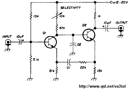
Here is another one

7219929600_1483761247.gif


[found at www .qsl .net /va3iul /Homebrew_RF_Circuit_Design_Ideas /Regenerative_Audio_Filter_WB6IOM .gif]

It uses 2 transistors though but it's ok, I would like to try it to see if it has better performance.
Any clues about the C1 and C2 values to use?
 
Last edited by a moderator:

Here is another one

7219929600_1483761247.gif


[found at www .qsl .net /va3iul /Homebrew_RF_Circuit_Design_Ideas /Regenerative_Audio_Filter_WB6IOM .gif]

It uses 2 transistors though but it's ok, I would like to try it to see if it has better performance.
Any clues about the C1 and C2 values to use?

No, it did not work at all, even if I made the first amp produce more gain. It did not get into oscillation or near it at all.
 

Status
Not open for further replies.

Similar threads

Part and Inventory Search

Welcome to EDABoard.com

Sponsor

Back
Top