Continue to Site

Welcome to EDAboard.com

Welcome to our site! EDAboard.com is an international Electronics Discussion Forum focused on EDA software, circuits, schematics, books, theory, papers, asic, pld, 8051, DSP, Network, RF, Analog Design, PCB, Service Manuals... and a whole lot more! To participate you need to register. Registration is free. Click here to register now.

capacitor calculation for ripple for smps i/p and o/p

Status
Not open for further replies.

deepakchikane

Full Member level 3
Joined
Jul 17, 2012
Messages
178
Helped
2
Reputation
4
Reaction score
2
Trophy points
1,298
Location
Mumbai, Maharashtra, India, India
Activity points
2,623
Dear all..
greetings..!!

i have been suffered with capacitor calculations.. as i m getting confused by reading too mch books..
i want a correct direction to select the capacitor to minimize the ripples... also the tolerances considerations for i/p and o/p...

waiting to hearing you sooon..!!
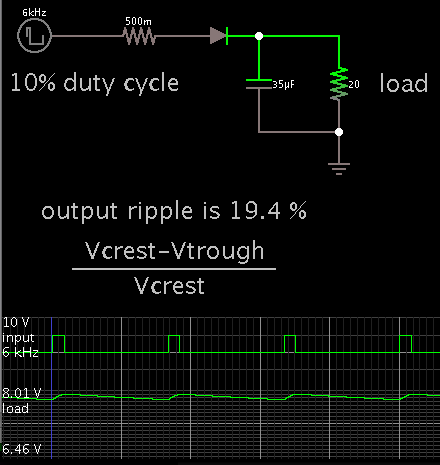
 

Rough calculations for output smoothing cap:

The capacitor charge drops a certain amount during an idle gap.
The amount of drop depends on the time constant, TC = R * C.
One time constant is the time it takes to change by 63% (by definition).

Suppose your load is 20 ohms. Operating frequency is 6 kHz.
You set a limit of 15% ripple. (A high figure but it shows up well on a simulated oscilloscope.)

Idle time can be as long as 1/6,000 sec. So the capacitor is permitted to fall 15% in 167 uSec.
This translates to 63% in 700 uSec. (To make things easy we use linear calculations.)

Therefore the time constant is .0007 second.
So solving TC = R * C, gives a cap value of 35 uF.

4350125100_1367452629.png


The 10% duty cycle creates an idle time which is close to the maximum, and the ripple is approximately the expected amount for our cap value.
 

Dear..
not satiesfied...:(

as one of my team mates keeps 940uF/450V CAP after bridge... n i am going to load that capacitor with 750 watts..

how that guy keep above cap after the bridge..??

he waz telling that...
ripple=vpp/loading power *(1/100(freq)*940uF)... SOMETHING LIKE THAT..

But he showed me exactly 17 v ripple by calculations and also practically wen we connect scope..
plz help me out hw..??


This suggests a high voltage supply. Supposing it is 450 V... then 750W calculates to 1.67 A.
Effective load 270 ohms.

1/100 is the idle gap time (time between current bursts of rectified 50 Hz mains AC).

A 940 uF cap, and 270 ohms, makes a time constant of .25 sec. Charge level would fall 63% in that time.
Therefore in .01 seconds it falls 2.5%. ( 63 * .01 / .25 ) (Although the discharge curve is not straight, we assume it is, to make things easy.)

2.5% of 450 makes 11.3 V of ripple.

This can only be a rough estimate. It's not a surprise that it's lower than your colleague's figure.

----------------------

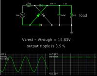
Consulting another source, here is a simulation:


It agrees better with your colleague's figure.
 
thank u sir..!!

- - - Updated - - -

another one doubt is that,
in dc to dc converter how i can calculate.??
by taking switch frequency of converter..??

consideration criteria for keeping ripple after bridge..??
1% is for the final o/p of converter...
 

another one doubt is that,
in dc to dc converter how i can calculate.??
by taking switch frequency of converter..??

Yes, the frequency is important. At high frequencies you do not need such a large value capacitor.

consideration criteria for keeping ripple after bridge..??
1% is for the final o/p of converter...

If this is mains AC frequency then you need a large capacitor. A round figure comes from the customary advice of 1,000 uF for every ampere you draw.

Or using time constant calculations...
Your ripple spec is 1%, inside a .01 second timespan.
This translates to a 63% drop in .63 sec. Therefore time constant is 0.63.
Suppose load is 270 ohms. Then the smoothing capacitor is 2,333 uF. ( .63 / 270 )

You can get more info from the list of similar threads at the bottom of this page.
 
Dear sir,

i agreed for the above explanation..

i want to calculate the o/p capacitor of my half bridge topology...

switch freq iz 45 khz..
converter worked at 380 v dc...


the o/p is loaded 1.7 amp @400v dc...

the o/p windings of 200v of 2 windings series together to produce 400v output...

please help me out..

i gone similar threads bt my fullfillments not completed..

like c=i*(1/f)/ripple... it coudnt helping me to find optimum solution..
 

switch freq iz 45 khz..
converter worked at 380 v dc...[/B]

the o/p is loaded 1.7 amp @400v dc...

the o/p windings of 200v of 2 windings series together to produce 400v output...

please help me out..

i gone similar threads bt my fullfillments not completed..

it coudnt helping me to find optimum solution..

Method #1.

There is always the method of installing a low value capacitor...
and watching to see if the ripple is too much...
and if it is then try a higher value.
Etc.

--------------------

Method #2.

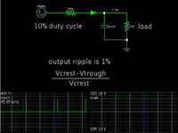
Or, a simulator is also useful for this purpose. 'Let the computer do the math.'

8.4uF. (Duty cycle 10% assumed).


----------------------

Method #3.

1% ripple on 400V is 4V. Then the formula:

C = 1.7 * (1/45000) / 4

= 9.4 uF

---------------------

Method #4.

The load calculates to 235 ohms. (400 / 17).

We have an idle period up to 1/45,000 sec. This is 22.2 uSec.

Ripple allowed is 1% during that time. Translates to 63% in .0014 sec. The time constant is .0014.

Divide by 235 ohms, gives us 6 uF for the output capacitor.
 

Status
Not open for further replies.

Part and Inventory Search

Welcome to EDABoard.com

Sponsor

Back
Top