Continue to Site

Welcome to EDAboard.com

Welcome to our site! EDAboard.com is an international Electronics Discussion Forum focused on EDA software, circuits, schematics, books, theory, papers, asic, pld, 8051, DSP, Network, RF, Analog Design, PCB, Service Manuals... and a whole lot more! To participate you need to register. Registration is free. Click here to register now.

Charging a 50 Farad Capacitor with Voltage Follower

Status
Not open for further replies.

Constructer

Junior Member level 3
Joined
Apr 11, 2017
Messages
30
Helped
0
Reputation
0
Reaction score
0
Trophy points
6
Activity points
290
The voltage feeding the follower will be 2.9v to 3.529v.
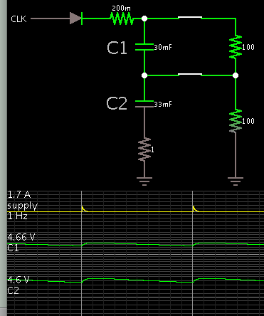
The "Transistor?" would charge a Capacitor.
BOPA1_circuit2.jpg
I envisage a diode would be need between Transistor and Capacitor for protection?
If so, is there a mathematical way to pre-compensate for the voltage drop across Diode, not shown?
BankDividerFollower.jpg
50F - 2x 100F Maxwell "BCAP0100 T01" Capacitors in Series:
https://www.mouser.com/ds/2/257/Maxwell_HCSeries_DS_1013793-9-341195.pdf
Rated Current 5A
Max. Current 18A
Max. ESR 30 mΩ
 

Capacitors in Series

It is chancey to charge capacitors in series. Can you be certain they start at the same voltage? Can you be certain their values are equal? It will be a good idea to add a resistor network designed to equalize charge on your capacitors.
 

Protection from what?

You do need some way to limit the current to the capacitor Rated Value (5A).

Sorry for that.
This is being made up as I go along in some areas.
Let us assume the Capacitor is rated for 50Amps.
 

It is chancey to charge capacitors in series. Can you be certain they start at the same voltage? Can you be certain their values are equal? It will be a good idea to add a resistor network designed to equalize charge on your capacitors.

would that mean charging with voltage divider?
Is there an example I could look at?

Thanks,
Gary
 

Hi,

Please show a complete schematic of your idea.
(with all devices like diode...)

And I don´t understand the various current specifications: 5A, 18A, 50A... where and when do they apply?

***
Charging a (big) capacitor with a linear circuit is lossy.
Maybe you should consider a switching circuit.

Klaus

I did not mention 50A, which reminds me of someone.
A switched power supply would be great if it followed a reference voltage created by voltage divider!

If you just wanted to charge your cells at a set voltage this should work fine.
This makes me think you would know how to make a switched power supply follow a changing voltage divider reference.
Why else would you as an idea?


Whats are you suggesting?
Gary
 

Hi,

Please show a complete schematic of your idea.
(with all devices like diode...)

And I don´t understand the various current specifications: 5A, 18A, 50A... where and when do they apply?

***
Charging a (big) capacitor with a linear circuit is lossy.
Maybe you should consider a switching circuit.

Klaus

- - - Updated - - -

Hi,

in post#4 you mentioned "50A"

To adjust a swtich mode regulator output (voltage) you just need to manipulate it´s feedback input. A simple OPAMP circuit does the job.
How to do this is frequently discussed here in this forum.

Klaus
 

The purpose of the design isn't clear. Referring to the schematic in post #1, it obviously misses a current limiting means to protect the transistors. Expected behavior with charged capacitor and power supply shut-off is another point.
 

It is chancey to charge capacitors in series. Can you be certain they start at the same voltage? Can you be certain their values are equal? It will be a good idea to add a resistor network designed to equalize charge on your capacitors.

Good point, and not something I had considered.
Balancing with resistors creates problems with dissipation.
If the Caps had 10% tolerance, could we say at least 20% higher voltage rating would cover the variation?
What rule would you use, for the safe use tolerances without resistor balancing.

- - - Updated - - -

Drive circuit is solved:
IMAGE 2017-04-12 03-32-52.jpg
Capacitor balancing is interesting because it also improves the performance/cost value.
Unless it can be done simply, it is just adding complexity for no benefit
 

Hi,

you take it as "solved"...
I see it is very critical.

* one diode carries current, the other not, therefore the voltage drop will not be the same
* the inverting OPAMP circuit is not driven properly. It may act like a floating input. --> wrong voltage, oscillating, ...
* why don´t you connect the feedback directely to the capacitor?
* why do you think you need a diode at all?

***
I wonder why you talk about balancing...
I don´t see capacitors connected in series..
And a balancíng circuit needs to push and pull, while your circuit can only push.

Klaus
 

would that mean charging with voltage divider?
Is there an example I could look at?

Simple example. You'll need to customize values to suit your own setup.

3554284800_1492063114.png


Notice the 10 percent difference in capacitor values but the tiny difference in voltage on them.
 

The resistors add dissipation and resistance.
Why not just use higher tolerance and or voltage capacitors.
There must be a general rule of thumb equation for choosing suitable capacitors?
 

A supercapacitor will be usually charged with constant current/constant voltage method, similar to a battery.

Energy efficiency is an objective in most applications, thus switched mode converters are a "natural" solution.

The circuits shown so far in this thread neither care for current limiting nor energy efficiency.

If the design objective is different (e.g. implement an analog controller circuit for test purposes rather than effective energy conversion), current limiting should be still provided for circuit self protection. A clear specification could clarify things.
 

Hi,

a more efficient voltage balancing circuit could be this:
(I never tested it, so treat it just as an idea.)
CBC.png

If it indeed brings a benefit, I don´t know.

Klaus
 

I didn't yet hear a clear question for balancer techniques in this thread, although term was mentioned en passant.

Smaller supercapacitor batteries like the said 50F size work well with a simple voltage limiting circuit parallel to each cell, like the below shown "Active Balancing" circuit from an Epcos/TDK application note. For higher capacitance, lossless switch mode balancers might be reasonable.

Active Balancing.png
 
The Linear/Analogue company balance IC proved to be over complicated with Monitoring system.
If all else fails there may be no choice but to have the Linear PCB modified.

Until that time I am looking at all options and possibilities to make this happen, will do a search.
Meanwhile, have you got any part numbers?

Thanks,
Gary
 

I didn't yet hear a clear question for balancer techniques in this thread, although term was mentioned en passant.

Smaller supercapacitor batteries like the said 50F size work well with a simple voltage limiting circuit parallel to each cell, like the below shown "Active Balancing" circuit from an Epcos/TDK application note. For higher capacitance, lossless switch mode balancers might be reasonable.

View attachment 137846

The problem I have found, is most balancing uses voltage differentiation after the cell is mostly charged, dissipating current through high cells.

A bank manufacture sets their voltage to 3.6v for increased cycle life.
This fits with the operating limits of Dissipative balance system.

My application uses oversized bank and low cell charge voltage by design.
It is worth a considerable investment to have balance function in the middle of cell charge cycle.
The extended cell life by matching the Charge/discharge envelope and increasing bank efficiency is what this is about.

Cheers
 

Series Capacitor balance.jpg

Source:
A Simple Active Method to Avoid the
Balancing Losses of DC Link Capacitors
**broken link removed**
 

I would recommend a DC-DC converter style with an
active current limit that is safe for both itself and the
cap. Most current mode controllers can be made to
deliver a maximum continuous current making it only
a power transistor selection and thermal management
problem.

I believe I have seen chips advertised that will balance
supercapacitor charge, but I can't recall the vendor.
However I do not think this matters, as Q=C*V and
if you are charging to a V endpoint, charge simply
follows (and why would you charge to less than
endpoint V, on one or the other?).

You might find that some lithium-ion battery charge
controller / DC-DC chips offer an elegant and cheap
solution (including cell balancing, dual-mode charge
control (CC->CV) and roughly-right voltage range).

I really appreciate your input.
And you seem to be correct on every point.

The fundamentals:
This experiment begins with a voltage divider.
16k resistor to Volts+ and 1K resistor to ground.
This creates a 1/17 reference that follows any changes in supply be design.
The variable 1/17 voltages is applied to the capacitor.

My question has been how best to create a simple voltage follower power supply.

Opp Amp with Darlington seems like a simple option.
I plan to include a diode between voltage follower output and capacitor,
and include a diode in the feed back loop to compensate for the voltage drop.
I believe the diode in feed back loop would need a 10k resistor to ground for flow?
If this resistor is required, I am now looking how it could be compensated for.
I will also need a current limiting resistor between Darlington/diode and Capacitor,
the same value resistor also goes in the feed back loop after diode.


The diode is included because the 1/17th Follower will be connected continuously for simplicity,
even though only serving a task in half the working period.
This means the 1/17th follower output could experience a few volts higher then its output from a particular cell in the sequence!

The diode may not be needed, but can it hurt to include it?
I found MUR1620CTRG ULTRAFAST RECTIFIER 16 AMPERES, 200 VOLTS
Common-anode pair in single package so their temps will track!
https://www.mouser.com/ds/2/308/MUR1620CTR-D-79742.pdf
Looking for a matching Darlington Driver.


Function After Capacitor is Charged:
The capacitor will be tapped into a cell in parallel.
During this time, any voltage it holds above the cell will transfer.
Before being disconnected from cell and charged back up to the 1/17th reference.
Repeat process for each cell.

Hope you can handle not getting the full story, I think the explanation suffices for suggestions.

this is not meant to find answers for other peoples balance problem or mine, just an experiment requiring simple cheap construction.
Let me know if you have any ideas that could fit my requirements.

Thank you very much.
Gary
 

Status
Not open for further replies.

Part and Inventory Search

Welcome to EDABoard.com

Sponsor

Back
Top