Continue to Site

Welcome to EDAboard.com

Welcome to our site! EDAboard.com is an international Electronics Discussion Forum focused on EDA software, circuits, schematics, books, theory, papers, asic, pld, 8051, DSP, Network, RF, Analog Design, PCB, Service Manuals... and a whole lot more! To participate you need to register. Registration is free. Click here to register now.

Need help :: FULLY-CONTROLLED SINGLE-PHASE SCR BRIDGE RECTIFIER: RL LOAD

Status
Not open for further replies.

Barbarawi

Junior Member level 2
Joined
Oct 13, 2012
Messages
20
Helped
2
Reputation
4
Reaction score
2
Trophy points
1,283
Activity points
1,468
Hi All ,,

I'm using ISIS Proteus in my Graduation Project ..

I could not find the Issue in my circuit when I use INDUCTOR with Resistance !!

my project about "How to control the DC motor by changing firing angle of the SCR thyristor"

so when I pressed to START .. the first cycle start from "90 degree" as I controlled it in my code in C "

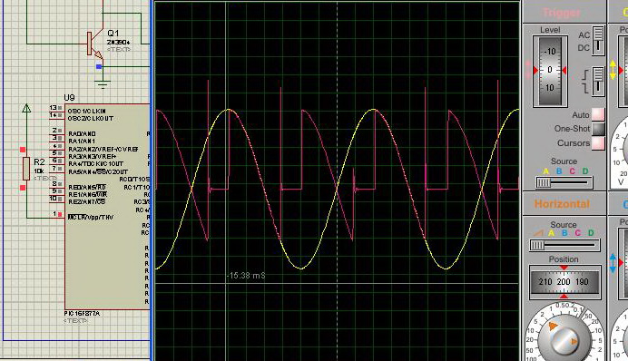
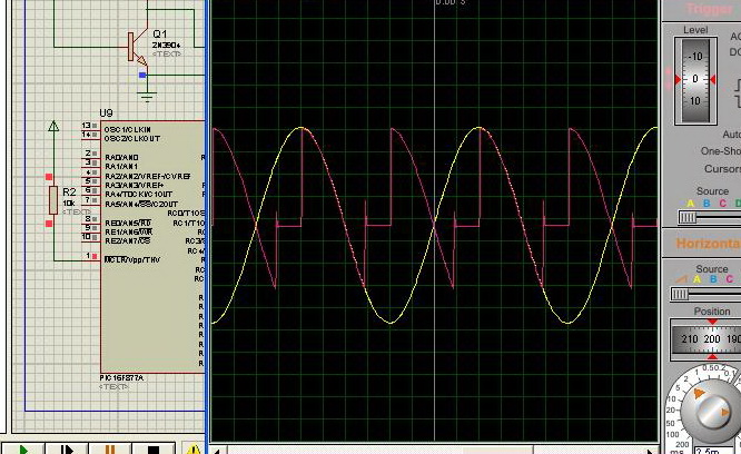
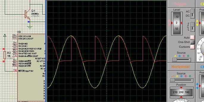
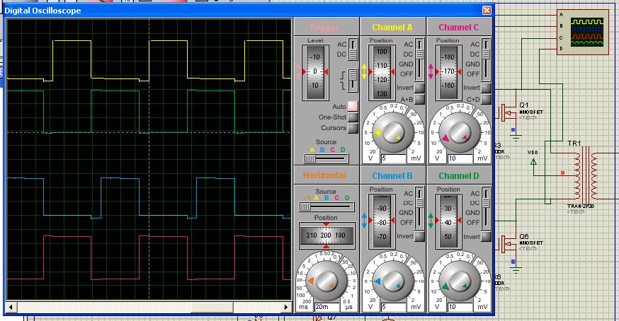
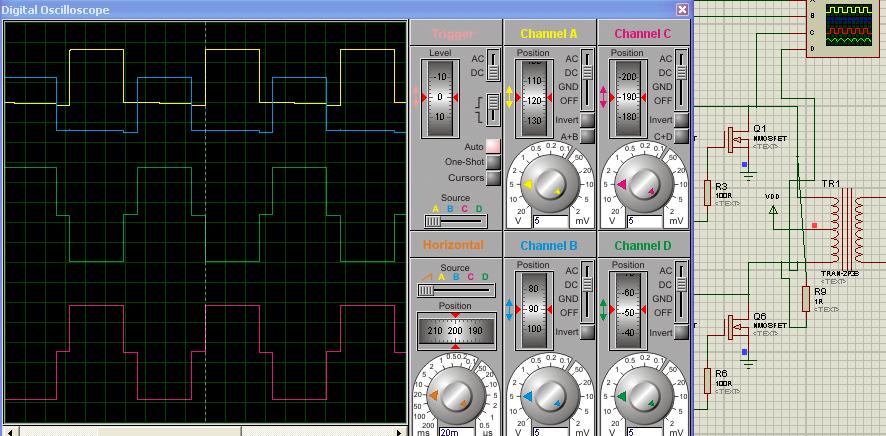
here are the result in the picture ~

Output.jpg

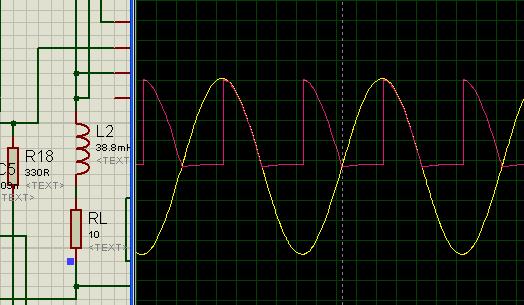
you can see from the picture the first cycle is only happened due to Inductor !! WHY ?! :shock:

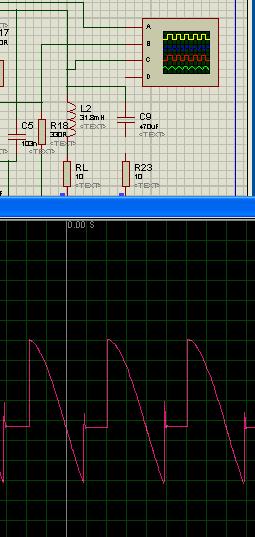
the Load parameter ::
R=10 Ohm
L=31.8 mH

what would be the problem ?!

for more info.
the circuit contained four 4- Opto-coupler to give the pulse that comes from the PIC16f877A to Optocoupler to SCR thyristor
each SCR have his own opto-

I need your expert :idea:
 

An scr shuts off when its current drops to a tiny amount.

Your first cycle shows the scr (or scr's) triggering as expected. Then all cycles after that show the scr's don't turn off. Yet the AC is rectified, apparently.

Is it possible the inductive lag is causing current to continue through the scr at odd times? This might be the case even when incoming AC goes to zero, because you might have scr's triggering when the other scr's are conducting. And vice-versa.
 

Please Mr.BradtheRad ..

could you give , the solution ?! How can I fix it !!

I tried to add RCD snubber circuit .. but nothing happened !
 

An example: Behaviour of inductor in simulation.
In this scope snap, upper two traces are gate drive 40% duty cycle. It felt strange to observe that output was 50% duty cycle on FETs drains( a square wave).


It was a matter of putting a load on output and it showed as expected (step sine wave).

The problem is, you should know, what you are doing.
 

I played around with your design with a 38.8mH load in series with 10 ohm resistor. See the output waveform.
7631127500_1352304739.jpg
 
Is that my project !!

How it works with you , I can't believe it :)

could you upload it and send it to me ... I try to make the output like this .. but unfortunately nothing happen in the full period of time .. just in the first cycle as I shown to you ..

please send it back with your design
 
  • Like
Reactions: ajrai

    ajrai

    Points: 2
    Helpful Answer Positive Rating
I used your hex code as it is, only modified hardware. As this is your graduation project, i like you to try it yourself. I give you hints what i did.
I changed pulse driving circuit and got this waveform,

You can see, there is big current lag.
After adding snubber circuit not yet optimized ,

And with output filter


This is with load, 31.8mH in series with 10 ohm resistance.
 
  • Like
Reactions: ajrai

    ajrai

    Points: 2
    Helpful Answer Positive Rating
you want me to try ?! hahaha I tried then try ... but nothing happen !!

also , I used snubber circuit but unfortunately nothing happened !

you just can tell me what your modification to my circuit?

any way thank you .
 
  • Like
Reactions: ajrai

    ajrai

    Points: 2
    Helpful Answer Positive Rating
Here it is. The values of components are not optimised as i put them by rough idea without calculating for their best values. You can see to it.
 

Attachments

  • graduation project.zip
    26.8 KB · Views: 332
sorry ... but when I run it it says there is an error !!

I tried to upload my HEX file .. and it's running .. but not like what you put it in the last post .. the output oops.jpg

what's the problem ... did you modify my code !! ?

- - - Updated - - -

thank you .. It's running now :))

thank you sir
 

The hex is from your file built on 2nd oct and is included in above zip file. The problem may be due to different versions of proteus in use with different models of components. Which version is yours? Mine is v7.10.
 
me too the same version

its working now thank you ... but I've question , why you change the Opto-coupler ?!
 

MOC3021 drives directly thyristor or triac. No need for extra parts. See its datasheet.
 
Last edited:

I had disconnected it !! there are ripple in output


why you telling me to disconnect it ?!
 

Experiment with snubber and filter components and current drive to MOC and gates and see behaviour.
 

Another Question !! the waveform output .. the first output in the positive but the second output should be in negative !!


you can see it from this website .. at the end of page see the graph .. Our simulation output just in positive ..

I need for one cycle from 0-90 in positive , and for 90-180 in negative !

see this : **broken link removed**
 

This is current lag due to inductance of load. C9 is filtering it acting like a power factor corrector. We are observing voltage on inductor. It is the same as second last graph on the page.
**broken link removed**
 
Last edited:

I don't get it !!

How we can have an output like this .. !!

mbroutv2.gif

- - - Updated - - -

but this for angle firing at 60 degree !!

- - - Updated - - -

the output from your file ... positive in whole cycle !

- - - Updated - - -

I need like this output out.jpg


Components C9 and R23 are filtering output. If they are removed, waveform is just the same except small spikes. This negative going voltages are not required as they cause power loss.

- - - Updated - - -

I need like this output View attachment 82648

This is for AC motor not DC motor.
 

No sir , Our project need this negative as full as positive .. !!

I post the photo that require for output !

did you see it ?! here it is out.jpg

- - - Updated - - -

Our project depends on DC MOTOR on the load

- - - Updated - - -

Also , I don't get it form your design ,, when you put the same component in the upper 2 thyristors but in other hand of the lower 2 thyristor in completely different connection form the opto-coupler into thyristor !! 8-O

you can see from your design U2 & U4 are the same .. and U1 & U3 are the same but not the same for all of the thyristor ?!

why we just but the same material for the full bridge ..
 

Status
Not open for further replies.

Part and Inventory Search

Welcome to EDABoard.com

Sponsor

Back
Top