Continue to Site

Welcome to EDAboard.com

Welcome to our site! EDAboard.com is an international Electronics Discussion Forum focused on EDA software, circuits, schematics, books, theory, papers, asic, pld, 8051, DSP, Network, RF, Analog Design, PCB, Service Manuals... and a whole lot more! To participate you need to register. Registration is free. Click here to register now.

[SOLVED] Is this circuit is working what I need

Status
Not open for further replies.

dadili

Junior Member level 2
Joined
Oct 31, 2011
Messages
22
Helped
0
Reputation
0
Reaction score
0
Trophy points
1,281
Activity points
1,413
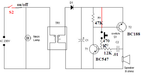
I need circuit for an electronic bell. Pushing a button creates impulse which is causing a sound on the speaker.
When you push a button, it is generating a basic frequency (1 kHz) in impulses. The time of pause of impulse is lowering proportionally with a length of duration how long button is pushed.

https://i.imgur.com/Hb2g8.jpg
 

Your circuit looks fine for the positive half cycle of the input A.C. signal
But what if the switch is pressed for the negative half cycle....
You need to get the replica of the same circuit below for the negative half cycle
Try to use the concept of Two diode rectifier
 

I don't see, how the oscillator will ever start. It misses an Ic current limiting means for T1.

The half-wave rectifier will be good with sufficient C1 value, although full-wave gives less ripple and thus a clearer sound.
 

forget it,
as no one can push for a period equal to half period of 25mS . the concept of errakeshpillai appears theoretical.
but we need to more consider that after push is released, whether the frequency would taper down.

depends more on filter cap value.
 
Last edited:

can anyone make the circuit that I need, I will pay?
 

Thanks to FvM, try this modified element, should work
have to select values
 

Attachments

  • alarm bell.PNG
    alarm bell.PNG
    57.6 KB · Views: 96
  • Like
Reactions: FvM

    FvM

    Points: 2
    Helpful Answer Positive Rating
I suggest a slight modification of the circuit


R3 is low resistance, e.g. 1-5 k, R4 is high resistance, e.g.100k to 1 Mohm and only needed to start the oscillator.
 

I'm worrying about AC 230V. would that make some problems?

FvM, now it should work just like how I described up there?
 

I'm worrying about AC 230V. would that make some problems?
Depends on. A typical door bell uses a bell transformer, so the doorbell push is operated with safe extra low voltage. This is an option for your circuit as well.
 

for test purpose apply 6V DC from a wall brick or adopter.and have only a diode and electrolytic capacitor.
have the switch shifted to DC input point. Diode helps reverse protection, and capacitor the oscillator return for the signal.
 

thank you all for your help
 

Status
Not open for further replies.

Similar threads

Part and Inventory Search

Welcome to EDABoard.com

Sponsor

Back
Top