Continue to Site

Welcome to EDAboard.com

Welcome to our site! EDAboard.com is an international Electronics Discussion Forum focused on EDA software, circuits, schematics, books, theory, papers, asic, pld, 8051, DSP, Network, RF, Analog Design, PCB, Service Manuals... and a whole lot more! To participate you need to register. Registration is free. Click here to register now.

[SOLVED] Can “J-hook” be soldered manually?

Status
Not open for further replies.

mmitchell

Advanced Member level 4
Joined
Dec 3, 2011
Messages
107
Helped
0
Reputation
0
Reaction score
0
Trophy points
1,296
Activity points
2,203
Hi,

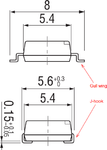
In comparing SMD switches, I found two types of leads: gull-wing and J-hook.
gullwing.png

Gull wing is like the normal type which has leads extends outwards, and is easy to solder. J-hook is new to me, and I found that the leads are bent inwards to beneath the switch body.

The question is can J-hook parts be soldered manually? If I am asking a solderer to do that with his soldering iron or station, it seems that there is no way to solder pads on both sides simultaneously; and since leads are bent beneath the body, after side A has been soldered the side B is also is also being pressed firmly on the PCB board with leads touching the pads. There would be no way to lift side B up to do the soldering without damaging the already-soldered side A.

Is it true? Is gull wing only used for machine soldering?


Matt
 

J-lead packages are pretty easy to hand-solder, as long as pitch isn't too fine (like 1.27 mm pitch on regular PLCC packages = okay), and you use a fine tip soldering iron. In case of doubt, have a look around on YouTube for some vids that show proper techniques.

The gull wing packages are less suitable for manual soldering as they usually have fine pitch, so you'd need a very fine soldering tip (+soldering wire), and still a good chance of bridging pins together. But there are effective techniques (Google for "drag soldering"), and bridged pins can be cleaned up with braided wire. Especially for small parts, be careful not to overheat them while soldering!

since leads are bent beneath the body, after side A has been soldered the side B is also is also being pressed firmly on the PCB board with leads touching the pads. There would be no way to lift side B up to do the soldering without damaging the already-soldered side A.
True - that's not what you do. Basically you stick the soldering tip into the 'cavity' between J-lead and board, and add soldering wire. When that melts, it flows underneath the "J" and a little behind it, so you get a good/strong solder connection. The iron's soldering tip stays on one side, and never goes underneath the "J" or where the melted solder winds up. Component stays flat on the board @ all times, and in essence it makes no difference whether other side was already soldered or not (in practice it does: if one side is soldered, component is kept nicely in place which makes it easier to solder other pins).
 
Last edited:
RetroTechie,

I am actually looking at a **broken link removed** (page 6, CHS-08A1) and its pitch is exactly 1.27mm. Would there be any problem for soldering them with a soldering iron/station?


Matt

---------- Post added at 11:08 ---------- Previous post was at 11:04 ----------

RetroTechie,

I see the updated comments in your post. This resolved my doubts, many thanks.

Matt
 

If you're reasonably good with a soldering iron (and it has a fine tip), this should be easy I think. The pins look quite thin (0.4mm?) so you'd have relatively large clearance between pins.
 
RetroTechie,

Confirmed. Thanks very much.

Matt
 

Status
Not open for further replies.

Part and Inventory Search

Welcome to EDABoard.com

Sponsor

Back
Top