prashkd85
Newbie level 4
Hello everyone,
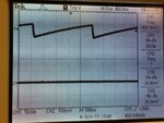
I am woking on a planar transformer desing and am using IR2085S half bridge resonator to generate 500KHz frequency which will then be used to drive the transformer. After going through the datasheet I have made the schematics as given in the datasheet **broken link removed** on page 1 and the only change I made was to replace C1 and C2 with a single resonator capacitor in series between pin Vs and the transformer HI side ( port 2 of the Transformer is grounded) . I applied 12V to the IC and ~18V to the Mosfets without connecting the inductor just for the testing purpose. From what I understand, using Ct as 100pF and Rt as 10K and using the given formula f = 1/2*Ct*Rt , IC should generate pulses at pin HO and at pin LO, synchronised in such a way that they pull the MOsfets Hi and Low to generate an AC signal @500KHz frequency at pin Vs. However, when I tried to test the ckt using oscilloscope, I am getting no pulses or freq. at either pins. The HO pin is constant hi and LO pins is constant LO whereas I should be getting a sine wave at the resonant frequency . Also, at OSC pin I AM getting freq. of about 408KHz [IMG_022].
I would appreciate if any1 who has experience with this IC can share their expertise.
Thanks
Attachments
Last edited: