Continue to Site

Welcome to EDAboard.com

Welcome to our site! EDAboard.com is an international Electronics Discussion Forum focused on EDA software, circuits, schematics, books, theory, papers, asic, pld, 8051, DSP, Network, RF, Analog Design, PCB, Service Manuals... and a whole lot more! To participate you need to register. Registration is free. Click here to register now.

Help with LED Picture. Complete newbie!

Status
Not open for further replies.

een54

Newbie level 5
Joined
Jul 15, 2011
Messages
10
Helped
0
Reputation
0
Reaction score
0
Trophy points
1,281
Activity points
1,368
Hello all,

I am completly new to electronics, save for attaching a light bulb to a battery using crocodile clips back in school.

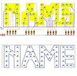
I wanted to make a gift for someone using LED's to spell out their name in a picture frame.

Something like this to give you an idea:

|----------------------|
| N A M E ' S |
| |
| R O O M | The frame messes up when I submit but just imagine the dashes as a picture frame
| |
| |
|_______________ |

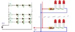
I would like the letters to be spelled out in LED's and possibly flash but not if this is going to be too difficult for a first timer.

Also would it be better to power this by battery or by a plug into the wall?

I would like this to be around 30cm by 60cm but the size really isnt important.

Can anyone give me details on what I would need, how I would go about it, and whether this is going to be possible at all?

I have access to a Soldering Iron and solder. And I have been looking at buying LED's on Ebay. I've done some research and I know I will need resistors but im unsure what type or which ones.

Thank you in advance for any help I receive and apologies if this is the wrong forum, but I thought this one looked like one for asking for help.

een
 

Easy… :grin:
If you wish to have several LEDs on at the same time it may be possible to connect them in series.
Start mounting the LEDs on the board. You may use a 9V battery.
Next step connect the LEDs in series by 3.
LEDs must have a resistor in series to limit the current to a safe value, so each group to use a small resistor.
Each group (3LEDs + resistor) will be connected in parallel to the power supply.
Take care, LEDs have polarized pins, so must be connected the correct way round, on LED anode to the other LED cathode.
The cathode is the short lead and there may be a slight flat on the body of round LEDs, you can see inside the LED the cathode is the larger electrode… :smile:
typically resistors values : 470 ohms / 680 ohms / 1 k

See the diagram.
 

Attachments

  • LEDs in series 2.JPG
    LEDs in series 2.JPG
    50.9 KB · Views: 101
Last edited:

Thanks for the speedy reply.

Ok I am a total newbie, so what kind of board would I be looking at? How big would it be?

And how much would it cost?(roughly)

Thanks again
 

You need a printed circuit board (or PCB) used to mechanically support and electrically connect electronic components.
 

Attachments

  • PCB.JPG
    PCB.JPG
    27.8 KB · Views: 84
  • Example NAME.JPG
    Example NAME.JPG
    213.1 KB · Views: 97
  • Like
Reactions: een54

    een54

    Points: 2
    Helpful Answer Positive Rating
You may find it useful to follow an established dot matrix character set. It will simplify layout on perf board or pad per hole board. Here's one for 5 X 7 characters.

5X7CharSet.gif
 
Thank you very much.

Still looking at PCB's but a little confused as to which one to get.

I was thinking about buying a starter kit, but this seemed a little more expensive
 

You can also use a piece of wood/plastic board, arrange the LEDs however you want to, and drill some holes for LEDs. Fix the LEDs on the back of board with hot glue, make all electrical connections on the backboard …
 
  • Like
Reactions: een54

    een54

    Points: 2
    Helpful Answer Positive Rating

No, maybe it's the best solution. No mobility, but no concern about the battery run out.


If we consider 60 Red LEDs, in rows of 3, each row using a 470 ohms resistor (for 5mA), we have a total of 20*5=100mA.
If we use a single battery, this will run out in one hour…
 
Last edited:
Most LEDs start to light up at about 2mA but look best from 10mA to 20mA so 5mA is on the low side. If you use a worst case estimate of 20mA and assume that each character needs 20 LEDs, you'd need 400mA at the LED voltage (2.1V for red), or 840mW of power per character. This doesn't include resistor losses but is useful for calculating power requirements. Obviously, you need to make some decisions about LED color and quantity and the power supply voltage and decide what level of current you want to run. If you're using blue, white, purple or pink LEDs, the voltage required per LED is nearly double that for red, for example 3.8V X 20mA would take 1.5W of power per character. If you ran 12 characters like that, you'd need a minimum of 20W power supply. That's only 1A at 24V.

If you're going to power from a mains powered supply, I'd recommend using a 24V switch mode supply. Higher voltage increases the number of LEDs you can put on each series string of LEDs and reduces resistor losses while keeping below 30V avoids the risk of shock. I see a couple of 24V 60W supplies at my favorite surplus vendor for $15.00 each though I sometimes find similar supplies much cheaper at thrift stores.

These supplies are for reference only since they're for U.S. line voltage.
 

You don't necessarily HAVE to install the LEDs on a piece of perfboard (perforated prototyping circuit board, like these). You could use a rigid piece of material, like thick cardboard or thin plywood/veneer, as the mounting surface for the parts. You would use a template of some kind (maybe the dot-matrix pattern suggested earlier), and draw the characters onto the board. That way, you can see exactly how the LEDs will look (draw small circles where the LEDs will stick through). Once you have the character and hole locations defined/drawn, use a drill bit that is big enough for the shell of the LED, but smaller than the ridged "collar" at the base of the LED (most round LEDs have a raised ridge on them). Determine the size by drilling a few test holes in a scrap piece of board. Dry-fit the LED into the holes, and find the best fit.

Once you know the hole size, and locations, it's time to drill the holes out. Once the holes are clear, you need to plan on LED location, orientation, and connections. Draw a scale layout of the board (put a piece of paper under the board, and use a pencil/pen to mark through the holes, onto the paper.. now you have an exact copy). You'll want to run 3 LEDs in series, and connect each set of three to a resistor, then back to the power source. Using your paper template, start penciling in which LEDs you'll wire together in sets of 3. The ends of each set (plus their resistors), will be connected together, run through a switch, and connected to the power supply. Like this (ignore the leading periods, the are just spacers):

Supply+...........................................................Supply -
..........|-- LED1 ---- LED2 ---- LED3 ---- Resistor --|

Once you have a wiring plan established, and have determined a suitable power supply (and associated resistor value), you can start installing the LEDs and wiring them up. Anode = + terminal, Cathode = - terminal. Connect the power supply to a switch (if desired), then the switch to the anode of the first LED(s). LED1 cathode to LED2 anode, LED2 cathode to LED3 anode, LED3 cathode to bias resistor, bias resistor to ground lead (power supply - terminal).

Put the LEDs in the holes. If they fit snugly, then you may not need to tack them in place (so they don't move while bending leads and soldering. If they want to move, use a hot glue gun to put a spot of hot glue on the back of the LED, to secure it to the board. Bend the leads, trim them, solder them, and test one set of LEDs out before doing the rest!! Route the power wires around cleanly. Use zip-ties to bundle them together, and then a blob of hot glue to tack the bundle down to the board. The best part about hot glue is that you can use the tip of the gun to warm it up, and loosen it up after it's hardened.

You could paint the board after you get it drilled, so that it's some desired color, rather than cardboard brown, or shows wood grain.

---------- Post added at 23:48 ---------- Previous post was at 23:15 ----------

Thanks all for the support

I have just bought: https://cgi.ebay.co.uk/ws/eBayISAPI.dll?ViewItemVersion&item=120469255311&view=all&tid=739717448002

I was wondering how many 9V batteries I would need to power say 60 of these LED's and how long it would last before the power ran out?

Is it difficult to hook it up to a plug to go into the electrical socket in the wall?

Which color of LEDs did you buy? That will affect the voltage & current calculations, as well as the number of LEDs in each string (high voltage LEDs will result in fewer LEDs per string, which means more strings, more resistors, more complexity).

If you look at the table above the shipping policy, it will tell you the Typical voltage for the various color of LEDs. They show that the parts are all run at 25mA (If is that parameter, I is current, f is forward direction, so If is forward bias current). 25mA will be really bright... like mentioned before, I'd probably bias them up around 15mA.

If you use a standard 12 VDC transformer to power this rig (using Red LEDs, so 2.0V per LED)....
12V / 2V = 6 LEDs, max. However, that gives you no extra voltage drop for the bias resistor, so we use 5 LEDs per string.
5 LEDs * 2V/LED = 10 volts of drop.
12V supply - 10V across the LEDs = 2V across the bias resistor
Now we use Ohms law to figure out the resistor value. V = I*R (voltage across a resistor, volts = current through the resistor, amps * the resistance in ohms).
So 2V across the resistor, and 15 mA (0.015 Amps) through the string...
2V = 0.015A * R(ohms)..... R = 133.3333 ohms. The nearest standard values are 120 and 150 ohms. I'd opt for the larger value. That will make the current be slightly lower than the target, but that's not all bad, since no two components (LEDs or resistors) are exactly alike.

Now to check the power dissipation of the resistor (V = voltage drop across resistor).
Power = V*I = V^2/R = I^2*R
So, power dissipated by the resistor will be:
P = V^2/R = 2^2 / 150 = 0.027 watts. If you use a standard 1/4W carbon leaded resistor... 0.25W >> 0.027W, so you have lots of margin, and won't be prone to burn up resistors.

Hope that gives you the tools/equations to calculate the number of LEDs in a string, when you determine your power supply, and how to figure out the bias resistor value.
 
Last edited:
  • Like
Reactions: een54

    een54

    Points: 2
    Helpful Answer Positive Rating
Once you know which LEDs and power supply voltage, you can use one of the online LED calculators or Ohms Law. I like this calculator because it allows large numbers of LEDs and gives you all of the power figures:
**broken link removed**
 
  • Like
Reactions: een54

    een54

    Points: 2
    Helpful Answer Positive Rating
You don't necessarily HAVE to install the LEDs on a piece of perfboard (perforated prototyping circuit board, like these). You could use a rigid piece of material, like thick cardboard or thin plywood/veneer, as the mounting surface for the parts. You would use a template of some kind (maybe the dot-matrix pattern suggested earlier), and draw the characters onto the board. That way, you can see exactly how the LEDs will look (draw small circles where the LEDs will stick through). Once you have the character and hole locations defined/drawn, use a drill bit that is big enough for the shell of the LED, but smaller than the ridged "collar" at the base of the LED (most round LEDs have a raised ridge on them). Determine the size by drilling a few test holes in a scrap piece of board. Dry-fit the LED into the holes, and find the best fit.

Once you know the hole size, and locations, it's time to drill the holes out. Once the holes are clear, you need to plan on LED location, orientation, and connections. Draw a scale layout of the board (put a piece of paper under the board, and use a pencil/pen to mark through the holes, onto the paper.. now you have an exact copy). You'll want to run 3 LEDs in series, and connect each set of three to a resistor, then back to the power source. Using your paper template, start penciling in which LEDs you'll wire together in sets of 3. The ends of each set (plus their resistors), will be connected together, run through a switch, and connected to the power supply. Like this (ignore the leading periods, the are just spacers):

Supply+...........................................................Supply -
..........|-- LED1 ---- LED2 ---- LED3 ---- Resistor --|

Once you have a wiring plan established, and have determined a suitable power supply (and associated resistor value), you can start installing the LEDs and wiring them up. Anode = + terminal, Cathode = - terminal. Connect the power supply to a switch (if desired), then the switch to the anode of the first LED(s). LED1 cathode to LED2 anode, LED2 cathode to LED3 anode, LED3 cathode to bias resistor, bias resistor to ground lead (power supply - terminal).

Put the LEDs in the holes. If they fit snugly, then you may not need to tack them in place (so they don't move while bending leads and soldering. If they want to move, use a hot glue gun to put a spot of hot glue on the back of the LED, to secure it to the board. Bend the leads, trim them, solder them, and test one set of LEDs out before doing the rest!! Route the power wires around cleanly. Use zip-ties to bundle them together, and then a blob of hot glue to tack the bundle down to the board. The best part about hot glue is that you can use the tip of the gun to warm it up, and loosen it up after it's hardened.

You could paint the board after you get it drilled, so that it's some desired color, rather than cardboard brown, or shows wood grain.

---------- Post added at 23:48 ---------- Previous post was at 23:15 ----------


Which color of LEDs did you buy? That will affect the voltage & current calculations, as well as the number of LEDs in each string (high voltage LEDs will result in fewer LEDs per string, which means more strings, more resistors, more complexity).

If you look at the table above the shipping policy, it will tell you the Typical voltage for the various color of LEDs. They show that the parts are all run at 25mA (If is that parameter, I is current, f is forward direction, so If is forward bias current). 25mA will be really bright... like mentioned before, I'd probably bias them up around 15mA.

If you use a standard 12 VDC transformer to power this rig (using Red LEDs, so 2.0V per LED)....
12V / 2V = 6 LEDs, max. However, that gives you no extra voltage drop for the bias resistor, so we use 5 LEDs per string.
5 LEDs * 2V/LED = 10 volts of drop.
12V supply - 10V across the LEDs = 2V across the bias resistor
Now we use Ohms law to figure out the resistor value. V = I*R (voltage across a resistor, volts = current through the resistor, amps * the resistance in ohms).
So 2V across the resistor, and 15 mA (0.015 Amps) through the string...
2V = 0.015A * R(ohms)..... R = 133.3333 ohms. The nearest standard values are 120 and 150 ohms. I'd opt for the larger value. That will make the current be slightly lower than the target, but that's not all bad, since no two components (LEDs or resistors) are exactly alike.

Now to check the power dissipation of the resistor (V = voltage drop across resistor).
Power = V*I = V^2/R = I^2*R
So, power dissipated by the resistor will be:
P = V^2/R = 2^2 / 150 = 0.027 watts. If you use a standard 1/4W carbon leaded resistor... 0.25W >> 0.027W, so you have lots of margin, and won't be prone to burn up resistors.

Hope that gives you the tools/equations to calculate the number of LEDs in a string, when you determine your power supply, and how to figure out the bias resistor value.

Thank you very much for this! Also to the poster after this one.

I bought half blue LED's and half yellow.

They should be here in 2-3 weeks but in the meantime I was thinking on just using a square of MDF for the board and drilling holes into it like you mentioned.
 

Thank you very much for this! Also to the poster after this one.

I bought half blue LED's and half yellow.

They should be here in 2-3 weeks but in the meantime I was thinking on just using a square of MDF for the board and drilling holes into it like you mentioned.

Using the method I outlined above, you should be able to calculate the proper resistor values for a string of blue or yellow LEDs (once you figure out a votlage source). I'd recommend keeping all of the LEDs on a string the same color, since their brightness will vary versus the amount of current. Similar colors and similar currents should yield similar brightness.

You may need to play around with the bias current on the blue vs. yellow strings. Our eyes don't see the whole color spectrum evenly (read this), so 500 lumens of pure yellow light will look brighter than 500 lumens of pure blue light. You'll probably need to experiment with running the two color strings at different currents to find the sweet-spot, and the amount of current that won't blind a passerby that looks right into the LEDs (running at 25mA will be really bright when viewed directly).

If you need some more help when the parts arrive, repost on here, or PM.
 

Hi guys i have an old 260w pc power supply, i was thinking.. maybe i could use the 12v rail from that to power this rig? Or is that going to be bad/not work?

Seasonic model: SS-235PS

DC output
+3.3v // +5V // +12v // -5V // -12V // +5V
14A // 23A // 8A // 0.5A// 0.8A // 1A


This just came into my head now so i will read back over your posts and try answer my own question

That should work, but might be a little overkill. Do you know (roughly) how many LED's you need to use, and what your desired bias current will be? From there, you can calculate the total current, and choose a power supply appropriately.

Additionally, check the output voltage of the power supply when it's unloaded (powered on, but not hooked up to any circuits). Those PC switch-mode power supplies (SMPS) are notorious for having higher voltages when no loads are applied (could be 5-10% higher than expected... so 12V might look more like 13V). That's part of why you use a current-limiting resistor with a string of a few LED's in series, and don't run your LED's right at the maximum current.
 

I have calculated i will need 134 LED's half blue and half yellow.

Not sure about the current :S

Still struggling to find an appropriate power supply for under £50 here in the UK. If anyone from the UK can recommend a site/shop i would be very grateful. I would even buy from ebay.co.uk from the right seller.

---------- Post added at 10:58 ---------- Previous post was at 09:48 ----------

**broken link removed**

This looks like it would be appropriate, although its 300mA so I would need resistors that take this down to say 20mA right? Not sure what resistors i have but i can check when i get home

Can you post the make/model information of your LEDs? The ebay link is dead (> 90 days old).

As for the current, that is more of the dependent variable... the current consumption is determined once you know the LED V-I characteristic curve, and what load resistance you're using. If you set the circuit up to draw 20 mA, then it will draw ~20 mA. If you have 5 strings that draw 20 mA, each, then all of them together will draw ~100 mA (20mA x 5).

Let's look at the specs for the LEDs, now that you know about how many you'll be using. Then we can compute power draw, and then determine what size of power supply you'll need.
 

(Hopefully) attached is a picture of the LED specs. I also have 12v Resistors apparently.

**broken link removed**

If the picture doesnt work here is the link to the item, i had to order some more. Scroll down to the section with a red heading titled "Round LED" for the specs.

If you could tell me whether the power supply i posted earlier is suitable, or point me in the right direction to one i can get in the uk, that would be awesome
Regards
 

Status
Not open for further replies.

Part and Inventory Search

Welcome to EDABoard.com

Sponsor

Back
Top