paulsxin
Newbie level 3
Hi All,
I have an issue with DC motor and Bluetooth.
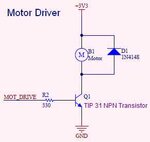
I'm using PIC, the motor driver is TIP 31 NPN transistor and 4 x AA rechargeable battery. Each battery is about 1500mAh.
The board has 2 modes, 1.simple run and 2.Bluetooh mode.

I have 3 motors and all are in good condition:
1. Motor A: 2.1 mAh
2. Motor B: 20 mAh
3. Motor C: 70 mAh
In "Simple Run" mode, the 3 motors run without an issue.
But when in "Bluetooth" mode with PWM, Motor B had difficulty in running and Motor C had a slight issue. Motor A is perfectly fine.
I have an android app to control the motor using bluetooh.
It looks like the current issue. But I already use 1500mAh battery.Somehow Motor C is run better than Motor B.
What may be the issue?
It looks like the Motor draw away the current from Bluetooth module and the microprocessor. This cause the signal send from the Android App break.
Or could it be the current from the motor fall back to the board?
What's the different about Mosfet and TIP 31 NPN Transitor?
Thanks!
I have an issue with DC motor and Bluetooth.
I'm using PIC, the motor driver is TIP 31 NPN transistor and 4 x AA rechargeable battery. Each battery is about 1500mAh.
The board has 2 modes, 1.simple run and 2.Bluetooh mode.
I have 3 motors and all are in good condition:
1. Motor A: 2.1 mAh
2. Motor B: 20 mAh
3. Motor C: 70 mAh
In "Simple Run" mode, the 3 motors run without an issue.
But when in "Bluetooth" mode with PWM, Motor B had difficulty in running and Motor C had a slight issue. Motor A is perfectly fine.
I have an android app to control the motor using bluetooh.
It looks like the current issue. But I already use 1500mAh battery.Somehow Motor C is run better than Motor B.
What may be the issue?
It looks like the Motor draw away the current from Bluetooth module and the microprocessor. This cause the signal send from the Android App break.
Or could it be the current from the motor fall back to the board?
What's the different about Mosfet and TIP 31 NPN Transitor?
Thanks!