afujian
Member level 4
Hi all,
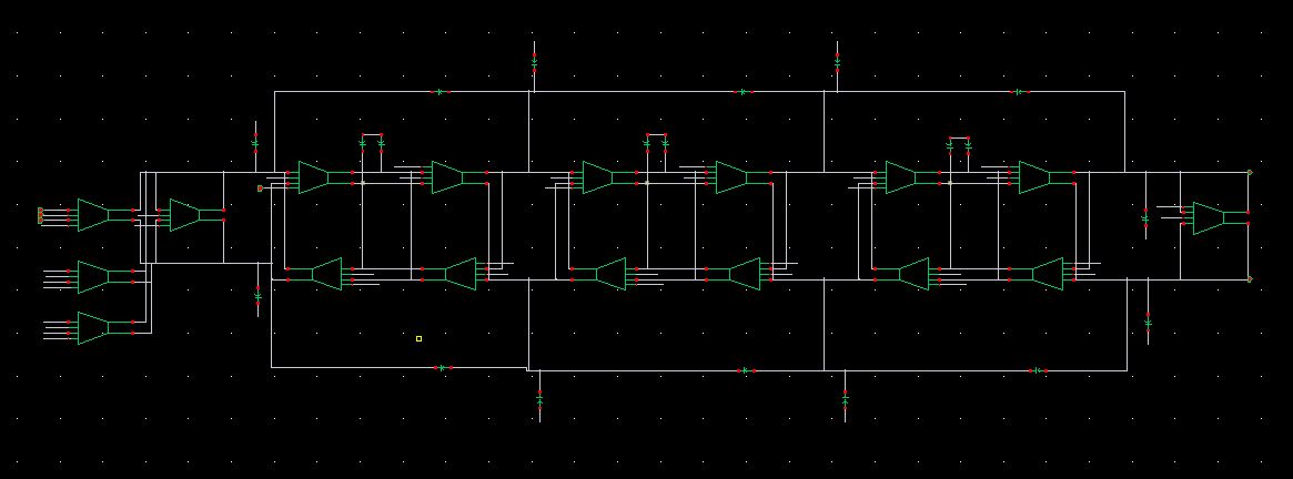
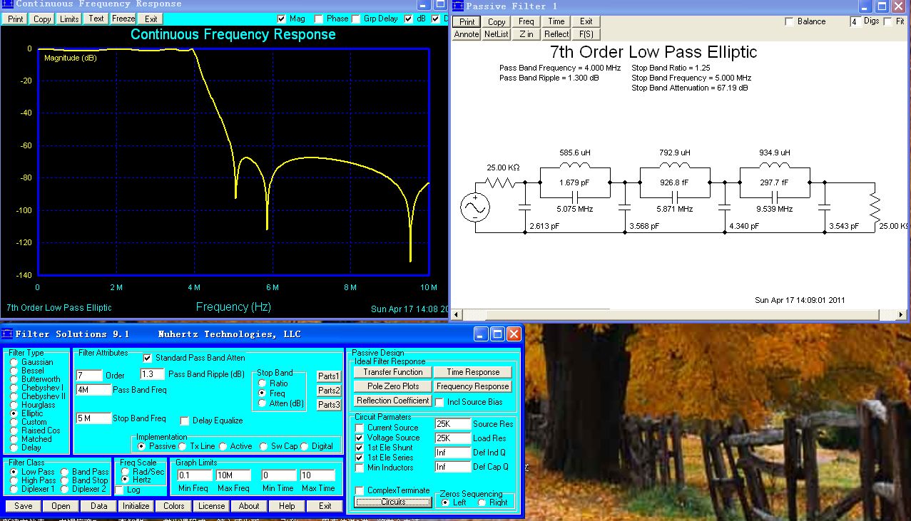
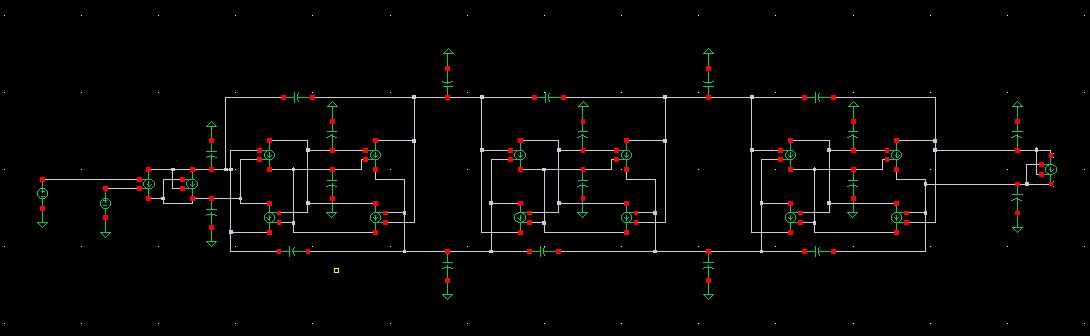
Recently,I am designing a 7th-order elliptic OTA-C filter,I got the prototype from the software of filtersolution , then replaced the passive components (resistor and inductor)with active components(negative feedback Gm cell for resistor and gyrator for inductor).
The spec of the passive filter is passband=4MHz, stopband =5MHz(Transition-band =1MHz),attenuation=40dB@5MHz.
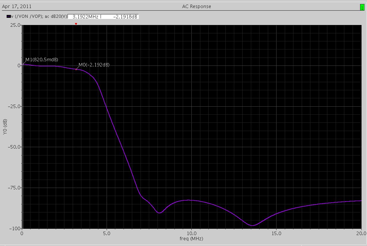
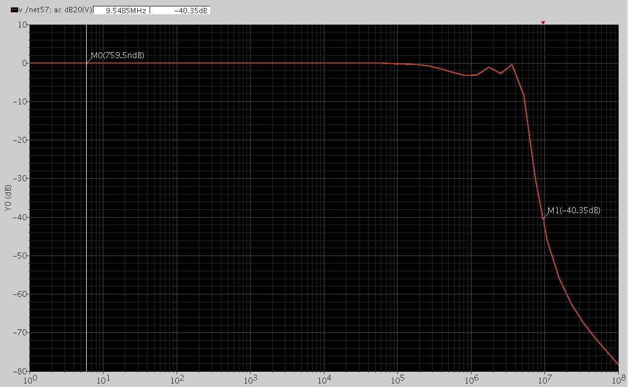
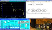
But,due to the simulation with spectre,the final active filter only has 3.2MHz passband, the attenuation at 5MHz is less than 30dB.
so,anybody can tell me the reason of the reducing of the passband and the attenuation.
I have tried for many days,but failed,there will be great appreciation for your help.
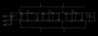
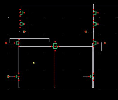
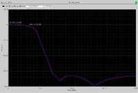
The pictures below are the circuit of the filter ,the gm cell,the ac response of and the response from the filtersolution respectively.
Recently,I am designing a 7th-order elliptic OTA-C filter,I got the prototype from the software of filtersolution , then replaced the passive components (resistor and inductor)with active components(negative feedback Gm cell for resistor and gyrator for inductor).
The spec of the passive filter is passband=4MHz, stopband =5MHz(Transition-band =1MHz),attenuation=40dB@5MHz.
But,due to the simulation with spectre,the final active filter only has 3.2MHz passband, the attenuation at 5MHz is less than 30dB.
so,anybody can tell me the reason of the reducing of the passband and the attenuation.
I have tried for many days,but failed,there will be great appreciation for your help.
The pictures below are the circuit of the filter ,the gm cell,the ac response of and the response from the filtersolution respectively.