gunnerunbeaten
Member level 2
i have to do a project, transmit and receive IR , don't use MCU + IR IC. only use IC to do it ? i don't understand principles to transmit and receive ?? please help me , what IC i can use ???
Follow along with the video below to see how to install our site as a web app on your home screen.
Note: This feature may not be available in some browsers.
it's remote 8 channel... i think i use 8 switch + mux 74153 + NE 555 for transmit module, is it ok ??? how do you think?do you want to send and receive IR as sensor..... or want to use as data transmitter like remote control
for senor i think the best one to be used is the IR of laser mouse in it you have two IR transmitter and two for receive ...but it is small range
for data (poor knowledge)
talking about remote control every button ha certain frequency adjusted pressing say '1' then frequency is send and it is received at the receiver and frequency determined (you must make sure about this knowledge)
 carrier)must visit)
...
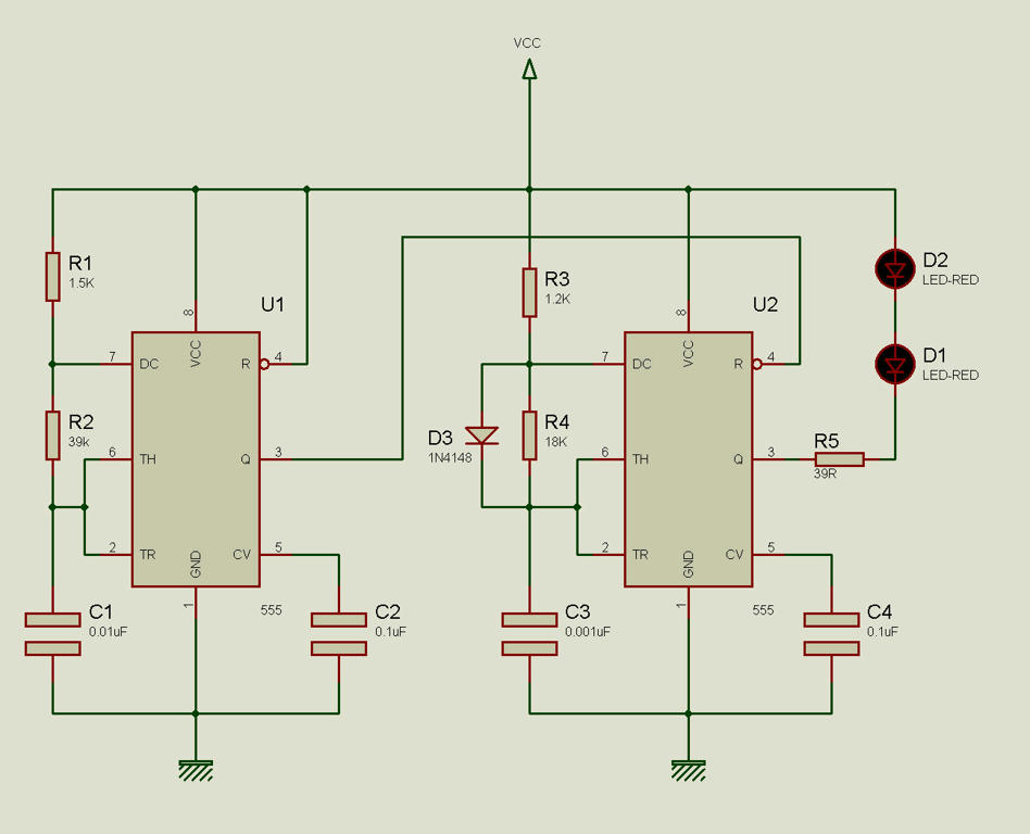
second 555
Time High: 831.600 ns Time Low: 12474 ns
frequency = 76Khz
So it will not work.
do you want to send and receive IR as sensor..... or want to use as data transmitter like remote control
for senor i think the best one to be used is the IR of laser mouse in it you have two IR transmitter and two for receive ...but it is small range
for data (poor knowledge)
talking about remote control every button ha certain frequency adjusted pressing say '1' then frequency is send and it is received at the receiver and frequency determined (you must make sure about this knowledge)
