Continue to Site

Welcome to EDAboard.com

Welcome to our site! EDAboard.com is an international Electronics Discussion Forum focused on EDA software, circuits, schematics, books, theory, papers, asic, pld, 8051, DSP, Network, RF, Analog Design, PCB, Service Manuals... and a whole lot more! To participate you need to register. Registration is free. Click here to register now.

Help! Can someone clarify to me how this converter circuit works?

Status
Not open for further replies.
I'm using UC3845...So, how much do I need? Sorry, Genome. I don't really understand the table as in there are many voltages..
Now, I'm testing my PIC. Everything is good.
My transformer will be delivered to my place by next week. Hopefully, everything will go smoothly.

Hmmm, I can get confused as well. You want one of the versions that has a duty cycle limit of 50% and then you want one that has the higher start up and operating voltages...

That would be the UC3844 50% 16/10

You'll notice that the ones with the higher start up voltage also have a wider operating range. This is to suit off-line conversion because they will normally be started with a 'bleeder' resistor from the main high voltage DC BUS. It gives them longer to get up and running.

For modelling purposes, if you have a UC3845 model, then you would need 9V. 17.5V for the UC3844.

If you want to operate at 20KHz then you would need a bigger transformer core/bobbin. It might/will end up being rather big. Yes you would change the RT/CT components to get the different frequency.

As FvM states... no you can't strip the core out of electrical wire and use it. You need the insulation and ordinary pvc insulated wire would take up too much space and the insulation itself would be too 'soft'.

How about I try and source some parts over here and get them shipped out to you?

I'll put together a more meaningful circuit diagram later.

Genome.
 
Sorry, Genome for confusing you. I would like to know during how much source I need to drive UC3845 in real circuit. Is it 9V? There are different voltages shown in the table.

I plan to run my DC chopper at 20-40kHz because the referred journal there stated 40k Hz. Actually I'm not sure whether I need to run both circuit (forward converter and DC chopper) at same frequency. So, I'm trying to test them at 20kHz.

If shipped to Malaysia, how much is the costs and how long would it take?
 

I would suggest the minimum operating voltage would be 12V.

I would really like you to consider operating the off-line section at... at least 80KHz. If you do not then as I say your transformer, and filter inductor, will become large. These sort of frequencies are not uncommon although I might be worried if you are thinking of building this on S-DEC.

I'm just checking on whether I can organise cores, bobbins, triple insulated wire and tape. The triple insulated wire should save you a lot of grief. Assuming it does not bust my bank then the cost to you will be £0.00. I shall leave you know later.

Genome.
 
Thanks Genome. Yea, I know that but the program that I wrote for my pic can only generate 20kHz with 50% duty cycle. When the frequency gets higher, the duty cycle tends to decrease.

Actually I need a different type of pulsing for my chopper and I'm beginner in pic. So, I try to write a simple program without involving much functions. The program can go up to 40kHz-50kHz but I don't know why the duty cycle changes.
 
Last edited:

I'm just waiting for someone to come back with a quote on the parts. Having mumbled it may be possible to have things working at a lower frequency. I have moved to a bigger core and naturally things became more relaxed. I wouldn't be certain about delivery times but possibly 7 days or slightly over. Hope that is not too long. I've asked for four sets of cores/formers so one for the transformer, one for the inductor and one for the inductor in your chopper with one to spare along with the wire as well. You will have some left over.

I don't know much about PICs myself other than occasionally looking at them. What are you actually trying to achieve with your chopper? I believe you have mentioned battery charging.

Genome.
 
Thank you, Genome. By the way, how about the tapes?
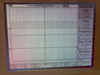
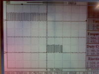
Actually I'm doing reflex charging current for battery. The DC chopper is to provide the reflex current due to the pulse. The pictures shown are the pulses coming out from PIC. These are from experimental results I obtained from my PIC.


This is for the chopper.

This is for the forward converter.
All running at 20kHz. The journal that I referred to only mention running chopper frequency at 40kHz but not for the converter. So, I'm not sure whether I should run them at the same or different frequency. But it is easier to run at same frequency.

I'm trying to find if there is any drivers can help me run that kind of pulse for my chopper.
 
Last edited:

Well.... Unfortunately my bright idea fell over. TEX-E would have avoided having to use tapes but it is 'expensive'.. However I think I now have a source for tapes, I know where to get the wires and I'll sort some cores as well. For the moment I would be inclined to forget about operating both converters at the same frequency. It looks like you are trying to synchronise the forward converter in your software and if you ignore that then you will save space and time for coding other things..

I'll just race off and redesign the transformer. Later..

Genome
 
Thanks Genome. It's alright to use tapes.

For the frequency, I think I need to test the circuit first.
 

OK. Just ordered the wire and a local transformer company is kindly going to send me some margin tape and 3M 56 polyester insulating tape of the 'correct' dimensions. I'll order some other bits and pieces from Farnell today...

Cores
Bobbins
UC3844
IRF720
Opto-Isolator

and perhaps some other bits just in case. Anything else you think you might need?

Genome.
 
Thank you very much, Genome. :lol:Actually I had bought irf840 and uc3845. The Opto-isolator is for the floating point of mosfet? I had bought the mosfet driver IR2101, I think that can be used. I'll just need materials for the transformer and hopefully, you won't spend too much.
 

Shopping is fun.. ;-)

The opto-coupler is for feedback secondary to primary. I might as well get you the other bits 'just in case'.

What about the filter inductor on your chopper circuit. Do you know what sort of value you might need?

I am including parts so you can make the output filter inductor for the forward converter which will be 600uH rated at about 2A, possibly more. If that would be suitable for your chopper then I'll just add the extra bits.

Genome.
 
LOL...:lol:

The filter inductor I'm using is 100uH but need to test. The output current is depend on how much the battery draws the current? I had checked the battery datasheet, the max charging current is around 1.36A. According to my simulation, 100uH will produce around 1.4A.

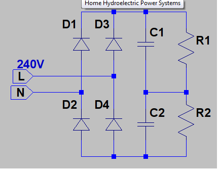
By the way, I had tested the front part of the forward converter today as shown in the picture. But I'm having problem with the ground because I did not connect the driver to MOSFET as there is no transformer for me to connect. The output that I obtained was the voltage output across the two capacitors keep increasing beyond the AC input. I wanted to connect battery ground to the circuit but I don't know where should I connect my battery live wire. So, do you know how to test the output of the capacitor? Do I need to connect the MOSFET?
 

Shopping done. I'm bound to have forgotten something but I'm sure your labs will have stocks of general purpose components. Just have to wait for the postman to deliver then I'll wrap it up and air-mail it to you. Can you PM me a delivery address?

I'm not sure about your last question and the picture isn't showing up.

Genome.
 
Sorry, I had forgotten to attach the picture. LOL

67_1298639886.png


Thanks, Genome.
 

I'm still not sure but I think you know that the voltage across the capacitors will rise to peak of the mains input or SQRT[2]xVRMS so with 240VRMS in you would expect about 340VDC across the capacitors.

Otherwise the secondary of your circuit, where the battery lives, will have no direct connection to the primary side. It will be isolated by the transformer and opto-coupler.

Genome.
 
Yaya...I think I need to ground my circuit to obtain 340V.

I had PM you my address.:-D
 

Now you have me worried!!!

All you need for your circuit at the moment is Live and Neutral and, unless you want to kill yourself, ideally you should be using at least an isolation transformer and preferably a variac as well. Without those in place, at least the isolation transformer, if you start waving Earth about the place things will go BANG...


Ask your college to provide the necessaries.. They should know what you are talking about.

If anyone else wants to add or correct then please do.

You might still manage to explode a few scope probes or components but Toasted CandleCookie is not something that should be on the menu!

Genome.

Being boring... unless you can reassure me that you, or others supervising you, understand as much I'll keep the bits for myself. :sad:
 
Last edited:
Oh.... OK, sorry to have over-reacted.

Genome.
 

Uhm, Farnell split the order so I have one part and am waiting on the other. In the mean time, as I suggested, I forgot something and got one part wrong so I had to place another order. Naturally I should be more focussed and organised but this is SMPS design and such concepts don't fit. Either that or I do not have the genetics for it.

Strange to say but quite a lot of the components have been manufactured in Malaysia so it would seem I am eating into our 'carbon footprint'.

Right... Having got my spreading behind into gear, and tip of hat to FvM for pointing out the upload of attachments and the existence of a UC3844 'equivalent' model in LTSpice, I've managed to sort out a 'better' Spice model for the thing.

I realise you have your own software suite but perhaps you might consider downloading LTSpice so you can have a play..

Linear Technology - Design Simulation and Device Models
https://ltspice.linear.com/software/LTspiceIV.exe

Here is the new model as nmod.zip

I 'robbed' a TL431 model from the LTSpice user group on Yahoo so hopefully if you unzip things in the same directory then things won't moan at you. I will check myself in a bit.

The LT1244 is not an exact equivalent, it is better, but it does the job. Neither is the PC817A but again it does the job. Caveats abound but,


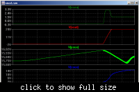
Start up,


I've 'cheated' on the primary auxiliary supply by using an IC statement to set the voltage on C3 to 15.75V, just below Under Voltage Lock Out.

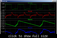
In regulation 250mA to 2A transient performance,


Not the fastest thing on the planet but seems to do the job.

Genome.
 

Attachments

  • nmod.zip
    5.3 KB · Views: 84
Status
Not open for further replies.

Similar threads

Part and Inventory Search

Welcome to EDABoard.com

Sponsor

Back
Top