Continue to Site

Welcome to EDAboard.com

Welcome to our site! EDAboard.com is an international Electronics Discussion Forum focused on EDA software, circuits, schematics, books, theory, papers, asic, pld, 8051, DSP, Network, RF, Analog Design, PCB, Service Manuals... and a whole lot more! To participate you need to register. Registration is free. Click here to register now.

programming AT89C51RC2

Status
Not open for further replies.

noamm91

Newbie level 3
Joined
Feb 20, 2011
Messages
3
Helped
0
Reputation
0
Reaction score
0
Trophy points
1,281
Activity points
1,312
Hello,

First of all I'm sorry about my bad english, I will try making as few mistakes as I can.

I develop a project for school which includes SPI communication between AT89C51RC2 and ADF4350 (Analog Devices's PLL).

I read the Datasheet of both and still cannot understand how should I set the communication.
I have several questions on this topic:

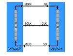
1. when I change the value of SPDAT (the SPI data register in AT89C51RC2) is the data automaticly starts going out on MOSI pin bit after bit? is every time there is rising edge one bit go out?

2. now about the ADF4350, does he waits until all 32 bits (4 Byte) gets in before he delivers them to the specific register (acorrding to 3 control bits)?

3.What happen if new data starts getting in on MISO before I read the current Data that in SPDAT? is it erase it automaticly or is it ignore any new data while i didnt read the current?
 

Answers
1.Every rising/falling(based on your selection) edge of the clock pulses the data will be shifted bit by bit

2. question again ?

3.New data on the SPDAT register destroys the old data
 
thank you for answering so rapido, But there is still some confusion on my side.

I'm not sure I understand well, Does every rising edge, the MSB of SPDAT (bit number 7) shifted out on MOSI pin and a new LSB bit is shifted in? is the value of the new LSB that shifted in is accorrding to the logic level on MISO pin when it was sample (when rising edge occured)?
and what if there were no data (no transmit going on) on MISO? what is the value of the LSB (bit 0) in SPDAT in that case?
Another question, is SPDAT register is bit addressable? meaning I can address to a spesific bit of the register with softwere (like SPDAT.5)?

I will thank you very much if you can try arrange all the confusion that going on in my head about the SPI with this uController.

Thank you!
 

I'm not sure I understand well, Does every rising edge, the MSB of SPDAT (bit number 7) shifted out on MOSI pin and a new LSB bit is shifted in?
data shifting will be depends on your selection, for example if you have selected rising edge and MSB first ,for DATA then SPI module will shift the data according to your selection

---------- Post added at 10:34 ---------- Previous post was at 10:29 ----------

Another question, is SPDAT register is bit addressable? meaning I can address to a spesific bit of the register with softwere (like SPDAT.5)?
SPDAT register is not a bit addressable

---------- Post added at 10:37 ---------- Previous post was at 10:34 ----------

during full duplex transmission
the master sends data on the MOSI line; the slave reads from the MOSI line
and the slave sends data on the MISO line; the master reads from the MISO line
 
for the diagram refer here
 

Attachments

  • untitled.JPG
    untitled.JPG
    33.2 KB · Views: 74
thank you,one more question

I'm using Keil uVision to write the code (in C) for the AT89C51RC2.
I understand that the SPI can be programed in polling mode or interrupt mode.
I like to get explainations about those 2 modes, how can I know what better for me, which one more easy to handle? and if posible I would want to see code expamples for how to sent a byte and recive byte in each mode.

I guess it might be a lot of trouble answering this question but I will thank you for any reference to my question.

Please make your answer as detailed as you can.
 
Last edited:

in polling mode
the PC will be keep on checking for the particular interrupt, if interrupt occurs PC will do next task

but in interrupt mode PC will not be checking for the interrupt, whenever there is a interrupt then the PC will go to the ISR and executes it

---------- Post added at 05:06 ---------- Previous post was at 05:00 ----------

example:
polling : while(!INT); //while no interrupt wait here itself if interrupt occurs do next task

interrupt:no while loop's //whenever there is a interrupt go to the ISR and executes it
 
Last edited:
Status
Not open for further replies.

Similar threads

Part and Inventory Search

Welcome to EDABoard.com

Sponsor

Back
Top