Continue to Site
Follow along with the video below to see how to install our site as a web app on your home screen.
Note: This feature may not be available in some browsers.
Reviving this thread again:Phaedrus,
I think the required level of accuracy almost demands low-side monitoring. Given the difficulties of the high-side approach, perhaps it may be easier to overcome the problems that caused you to reject the low-side method?
Cheers
[/QUOTE]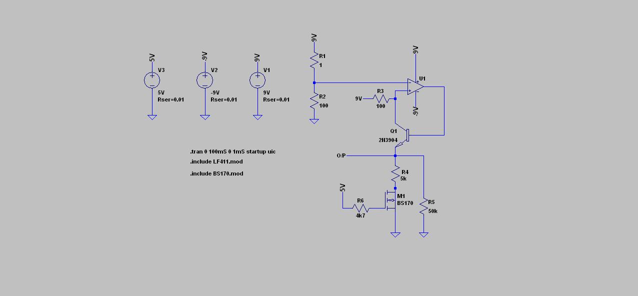
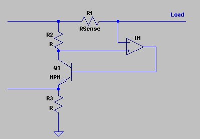
See EDN magazine "design ideas" section 12/15/2010 edition,
Pg43 for a decently simple high side monitor. It uses a local
regulator (zener shunt and resistor) to make the high side
negative supply. You might substitute a small MOSFET for
the Darlington and eliminate the residual base current errors.
Please notice, that according to the LF411 datasheet, the OP is not guaranteed to have the positive supply included in the common mode range.

The EDN circuit is here
guaranteed[/I] to have this capacity, but the internal circuit indicates that it will for the likely range of this application.
Hi Humber ,
Is the graph I posted the correct one to check this ?Does this mean that the graph is characterized and not actually tested ?
Thanks !!
The EDN circuit is here
guaranteed[/I] to have this capacity, but the internal circuit indicates that it will for the likely range of this application.
Yes. Phaedrus, that is the correct chart. The margin is small, and perhaps cannot be guaranteed to some particular specification, because there will be some change in the offset voltage as the rail is approached, rather than failure of the common-mode capability. Again, it depends on the accuracy you seek.
How do you know that it can't fail completely?The margin is small, and perhaps cannot be guaranteed to some particular specification, because there will be some change in the offset voltage as the rail is approached, rather than failure of the common-mode capability. Again, it depends on the accuracy you seek.
I didn't read the comment on degraded performance near the positive rail. I agree, that it sounds like like a guarantee for non-failure. But getting no exact number about the behaviour, I personally won't rely on it. According to my experience, most trouble in rework respectively redesign is with circuits, that should work according to typical data and other optimistic assumptions. And some is in addition with properties, that should never show, if the datasheet would be true. The bad thing with problems related to process variations is, that they show suddenly and unexpected, but are often affecting a full production lot, because all chips are from the same reel.
There is an inconsistency between the text and the chart. That is not uncommon.
The text says:
"The amplifier will operate with a common-mode input voltage equal to the positive supply; however, the gain bandwidth and slew rate may be decreased in this condition. When the negative common-mode voltage swings to within 3V of the negative supply, an increase in input offset voltage may occur."
Hi Humber,FvM ,
The discussion has become a tad esoteric, atleast for me I think.
1)"When the negative common-mode voltage swings to within 3V of the negative supply, an increase in input offset voltage may occur."
I could not understand this , what does the "negative common-mode voltage" mean ? Is it the voltage at the load side of the sense resistor(for high side sensing) w.r.t. V- supply of the OpAmp? So if this voltage is always greater than 3V of V-,then there would be no offset voltage increase ?
2) I don't think you will find data on input offset against common mode voltage, so that would limit the device to operation within 3V of the rail, if guaranteed performance is a demand.
So if I am using an op-amp powered by +9V/-9V , then the common mode voltage should be less than 6V to get the specified offset ?