Continue to Site

Welcome to EDAboard.com

Welcome to our site! EDAboard.com is an international Electronics Discussion Forum focused on EDA software, circuits, schematics, books, theory, papers, asic, pld, 8051, DSP, Network, RF, Analog Design, PCB, Service Manuals... and a whole lot more! To participate you need to register. Registration is free. Click here to register now.

control of dc motor through microcontroller via dual converter

Status
Not open for further replies.

yasir31

Newbie level 5
Joined
Dec 30, 2010
Messages
8
Helped
0
Reputation
0
Reaction score
0
Trophy points
1,281
Activity points
1,340
hello,
I am a beginner in programming and i have written an algorithm for generating pulse through micro-controller for triggering of SCR after a specific delay, but i want my code to run just twice per single AC cycle, i dont know how to do it.
( i am using 89c51)

Can anybody help???
 
Last edited:
thnx but i wanna know what should be the code or algo to run the program just twice per cycle.........????
 

i once have made a fan controller for me couple of years b4
see, here the speed of motor depends on duty cycle ,after your scr trggering
so to efficiently control motor
our strategy as follows
1_ have hz measure (to get full on time for cycle)
2_now trigger after x% of time where x= 0 for full speed and near to 100 for lowest speed
3_if u like try an optocoupler
just develop ur code having these simple things in mind
my circuit worked perfectly,i made it on 10f200 with some three leg ,i forgot

---------- Post added at 11:37 ---------- Previous post was at 11:35 ----------

hope u get what u want
 

Hi,
By twice in an AC cycle, I assume that you mean once in the positive cycle and once in the negative cycle. Can you please explain what you meant? If you mean how to generate that delay only twice per cycle, do this:

1) Have the delay generator as a subroutine. It would be better if the delay was using timer, but if there is no other task to be done, software delay would be just fine.
2) Detect zero-crossing using only micro-controller or you can use external circuitry.
3) The zero-crossing triggers an interrupt.
4) On the interrupt you set a flag or something that, when returning to the main program calls the delay subroutine.
5) After the delay elapsed, send a firing pulse to the SCR/Triac either non-isolated or by using an opto-triac for isolation. For opto-triac, look at MOC3021.
6) Wait for next zero-crossing.
7) Set the same delay time again.
8) Fire after the delay has elapsed.
9) Change the delay if required.
10) Wait for zero-crossing and repeat.

But why are you doing this if you want to control DC motor? AC motor, I understand, but for DC, you could just use a BJT/MOSFET and PWM that.

How would you fire in the negative cycle using SCR? You would need two SCRs.

Hope this helps.
Tahmid.
 
Thanks guys,

Actually i am looking to trigger two SCR bridges one by one, by that i mean only one bridge circuit will operate at a time. i have connected a zero crossing detector as the input of micro-controller, and yes i mean to run the program once in the positive cycle and once in the negative cycle, in other words the program should not run again before the input is changed(after running once), obviously after each half cycle the input will change.

hope now you understand my question.
 
Last edited:

tahmid point out right thing,,if u have to control dc motor ,the most efficient thing is to pwm
in my opinion also u have to control by pwm
full wave rectifier__full wave cap then switching device will solve this.

simple techniqes are the most efficient one :)
 
Hi,

I think the algorithm should be something like:

1) Detect zero-crossing.
2) Determine if it's positive or negative half-cycle.
3) Calculate required delay time for phase angle control.
4) Fire one set of SCRs(2 from the left bridge or 2 from the right), depending on required direction.
5) Wait for next zero-crossing.
6) Determine if it's positive or negative half-cycle.
7) Use the same delay time for phase angle control as used in first half-cycle.
8) Fire the other set of SCRs(the other 2 from left bridge or other 2 from right bridge), depending on required direction, maintaining the same direction as in the first half-cycle.
9) Update required delay time for phase angle control.
10) Restart the process.

I think you want to control both speed and direction, that's why you have 2 bridges, otherwise 1 bridge would be enough. Am I right?

Hope this helps.
Tahmid.
 
Thanks Tahmid,
yes i want to control the speed and the direction of motor, i have followed the algo but what should be this zero crossing thing......i have used lm 741, it is causing problem( it provides only positive volts to input of microcontroller) i can not detect zero crossing through it.

plz help...

i am giving the link to proteus simulation pic and code(both are not working)

https://obrazki.elektroda.pl/65_1294082141.jpg
 
Last edited:

Hi,
PIC can't sense negative voltage. Plus your 741 will have an output of 12 and -12v minus offset. So, that will fry the PIC. I will try to post a circuit for zero-crossing. Anyway, the code you sent, I can't help in that, because I don't use 8051, so, I don't understand anything you wrote.

Hope this helps.
Tahmid.
 

thanks tahmid,
its okay about code because i have modified it and it is running nicely, now the lm 741 which i am using as zero crossing detector provides the required output (square wave) if i simulate it in proteus, but when i connect it to micro-controller it does not show any output i-e it gives only 0.5 volts or less as output (to the input port of micro-controller).
i do not know what to do and what is wrong.......
plz help...
 

Hi Tahmid,
i tried but could not attach proteus file, i do not know how to attach it only gives me the option to insert image,
plz tell me how to attach proteus file or if you can send me your email address so that i can mail you the file(that will be very kind of you)......????????
 

Hi,
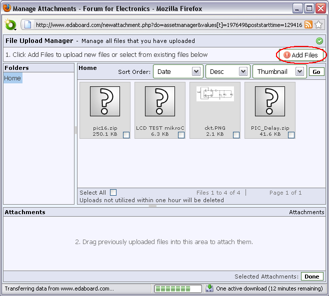
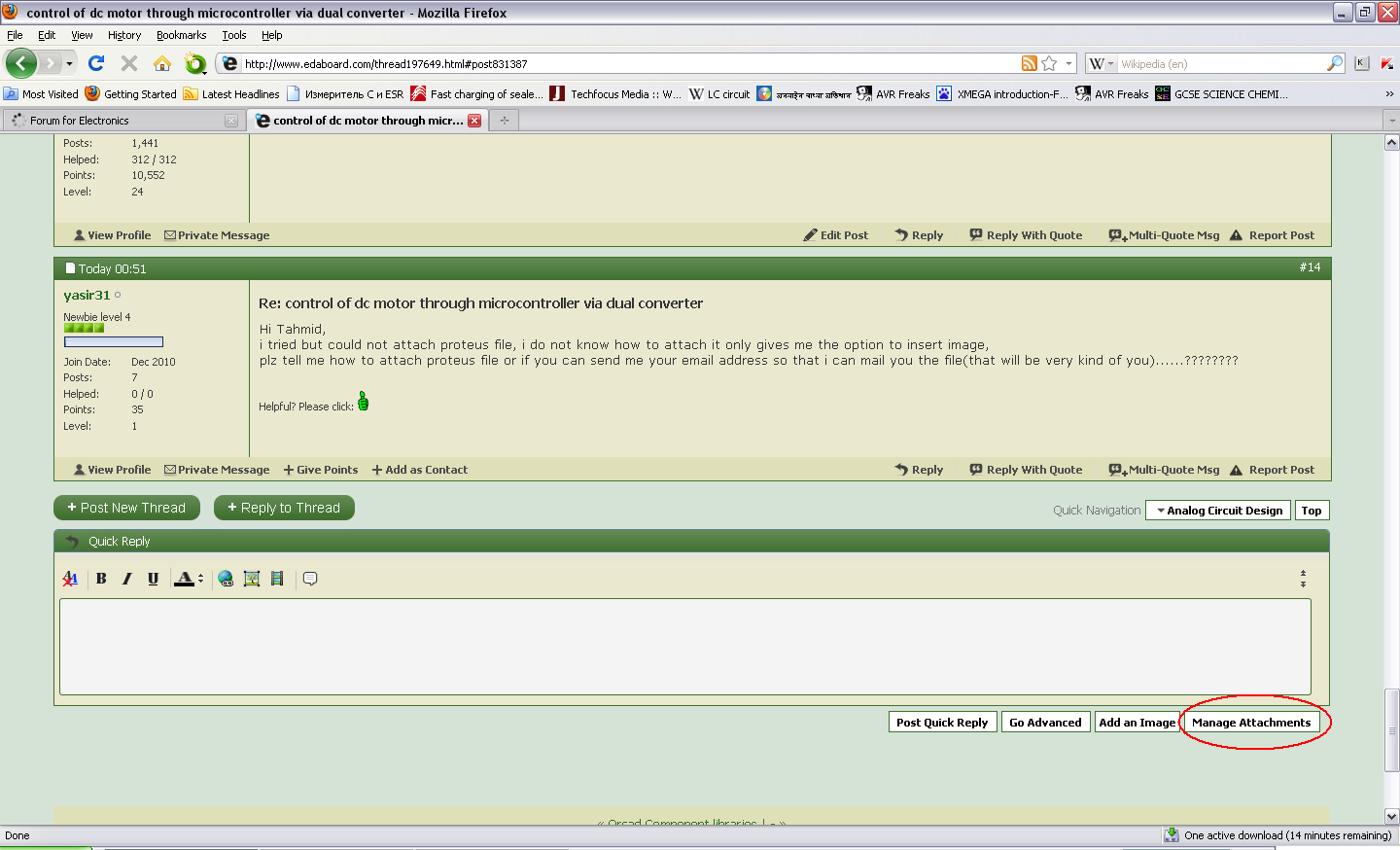
Here are 2 steps to get you started to attaching a file:


1. Click "Manage Attachments":


90_1294167850.png


2. Click "Add Files":


40_1294167850.png


Hope this helps.
Tahmid.
 
thanks Tahmid,

i have attached the file, when i connect this circuit to 89c51, the output of this circuit becomes approximately zero(0.5 volts or less). plz tell me what to do????
 

Attachments

  • new1.zip
    19 KB · Views: 124

Status
Not open for further replies.

Similar threads

Part and Inventory Search

Welcome to EDABoard.com

Sponsor

Back
Top