Continue to Site

Welcome to EDAboard.com

Welcome to our site! EDAboard.com is an international Electronics Discussion Forum focused on EDA software, circuits, schematics, books, theory, papers, asic, pld, 8051, DSP, Network, RF, Analog Design, PCB, Service Manuals... and a whole lot more! To participate you need to register. Registration is free. Click here to register now.

Help on PIC serial UART (mikroC)

Status
Not open for further replies.

lloydi12345

Member level 4
Joined
Aug 31, 2010
Messages
77
Helped
5
Reputation
10
Reaction score
5
Trophy points
1,288
Activity points
1,953
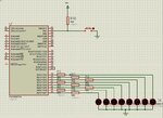
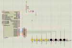
Hi, I am new on serial programming using UART and this is my first attempt to program it. I used to program on ASM but now I wanna give it a shot on mikroC. I hope someone can tell me where my mistake is. RD0 - RD3 is supposed to light and RD4 - RD7 is supposed to be off whenever my push button is unpressed. When the push button is pressed, it does the opposite.

Code:
unsigned int i;

void main() {
            PORTD  = 0;
            TRISB  = 1;
            TRISD  = 0;
            
            UART1_Init(9600);           // initialize USART module
                                         //  (8 bit, 9600 baud rate, no parity bit...)

            if (PORTB = 0x01 ){     //if push button is unpressed
                   UART1_Write(0b00001111);
                   Delay_ms(100);

                   while (1) {
                         if (UART1_Data_Ready()) {
                         i = UART1_Read();                  // read the received data

                         PORTD = i;
                         Delay_ms(100);      //light LEDs on RB0 - RB3
                         }
                   }
             }
             
             else  {                //if push button is pressed
                   UART1_Write(0b11110000);
                   Delay_ms(100);

                   while (1) {
                         if (UART1_Data_Ready()) {
                         i = UART1_Read();                  // read the received data

                         PORTD = i;
                         Delay_ms(100);    //light LEDs on RB4- RB7
                         }
                   }
             }
                   
                   
}
 

Attachments

  • Capture.JPG
    Capture.JPG
    117.4 KB · Views: 195

what is the exact problem?
also plz give the code of functions u used in main ()
 
hi lloydi12345
here is a sample for u
ur doing library function syntax error
also review some basics of c
 

Attachments

  • uart.rar
    20.6 KB · Views: 205
The problem here is that the LED pattern is not right. The pattern is not changing even if i press the button. Sorry, I used to program on ASM so I think I'll have problem with C. I hope you can bear with me.

---------- Post added at 19:52 ---------- Previous post was at 19:44 ----------

hi lloydi12345
here is a sample for u
ur doing library function syntax error
also review some basics of c

whew, your code works great majoka.. I have few questions though..

Is it alright on USART if i'll try for example, when a character is send by uart for example "A", then there would be certain command for it to light LED. Then if I'll send another character "B" it will do another command to light the LED. Will if statements do it?
 

yes lloydi12345
it is possible
just u has to use if else statements
when u receive a character compare if it is 'A' then a specific pattern of led on on port
if it is 'B' then another sequence sent to port
 
yes lloydi12345
it is possible
just u has to use if else statements
when u receive a character compare if it is 'A' then a specific pattern of led on on port
if it is 'B' then another sequence sent to port

Thanks again majoka

regards,
lloydi12345
 

I am also experiencing similar problem. Did you overcome this problem?
 

hi lloydi12345
here is a sample for u
ur doing library function syntax error
also review some basics of c

Can send me the sample.
Thanks.

I tried UART within 1 PIC is working. But not working with PIC to PIC communication.
BTW, the clock is different between the 2 PICs, but the baud rates are both set at 2400 bps.
 
Last edited:

@ jcwh
I tried UART within 1 PIC is working
how u try this
generate a 2400bps and then connect it with pc
often people do mistake in connections with pc
u has to use max232 and follow this sequence of connections
**broken link removed**
after opening the link click on description
 

Sorry, my typo mistake. I am actually referring problem between 2 PIC16F MCU communicating through a RF 434 modules.

Do i need a MAX232 IC if i am communicating between 2 PIC MCUs through an one-way RF module?
 

@ jcwh

u not need of MAX232
Connect 1 pic tx pin with the module rx pin
now connect 2nd pic rx pin with the tx pin of module
that's simple
 

I received garbage data at the receiver side through the 434MHz RF module.
When transmitter is displaying 1 on the LCD,

I received the following random numbers on the receiver, i:
0, 224, 240, 192

I couldn't make up what it means.

I have attached the DSN file. It works in the simulation in Proteus. But not working in the actual circuit.
I even tried connecting the TX of PIC16F628A to the RX of PIC16F886, but still not able to get the data as in Proteus.
Anyone can enlighten me what went wrong and how to rectify it?

I have the following codes:
Transmitter PIC16F628A:
// LCD module connections
sbit LCD_RS at RB0_bit;
sbit LCD_EN at RB3_bit;
sbit LCD_D4 at RB4_bit;
sbit LCD_D5 at RB5_bit;
sbit LCD_D6 at RB6_bit;
sbit LCD_D7 at RB7_bit;
sbit LCD_RS_Direction at TRISB0_bit;
sbit LCD_EN_Direction at TRISB3_bit;
sbit LCD_D4_Direction at TRISB4_bit;
sbit LCD_D5_Direction at TRISB5_bit;
sbit LCD_D6_Direction at TRISB6_bit;
sbit LCD_D7_Direction at TRISB7_bit;
// End LCD module connections

sbit SW1 at RA1_bit;
sbit SW2 at RA2_bit;

char uart_rd;
unsigned short i = 0;


void main() {
CMCON = 7; // Disable Comparators
TRISA = 0b00000110;
TRISB = 0b00000010;

Lcd_Init(); // Initialize LCD
Lcd_Cmd(_LCD_CLEAR); // Clear display
Lcd_Cmd(_LCD_CURSOR_OFF); // Cursor off
Lcd_Out(1,1, "RF Transmitter");
i = 0;

UART1_Init(2400);
Delay_ms(100);
Lcd_Chr(2,1, i+48);

do{
UART1_Write(i); // send data,
Delay_ms(500);

if (!SW1)
{
i++;
Delay_ms(500);
Lcd_Chr(2,1, i+48);
}
if (!SW2)
{
i = 0;
Lcd_cmd(_LCD_CLEAR);
Lcd_Out(1,1, "RF Transmitter");
}

}while(1);
}


Receiver PIC16F886:
// LCD module connections
sbit LCD_RS at RB0_bit;
sbit LCD_RW at RB1_bit;
sbit LCD_EN at RB2_bit;
sbit LCD_D4 at RB4_bit;
sbit LCD_D5 at RB5_bit;
sbit LCD_D6 at RB6_bit;
sbit LCD_D7 at RB7_bit;
sbit LCD_BL at RB3_bit; //define LCD_BL as RB3
sbit LED_A0 at RA0_bit;
sbit LED_A1 at RA1_bit;

sbit LCD_RS_Direction at TRISB0_bit;
sbit LCD_RW_Direction at TRISB1_bit;
sbit LCD_EN_Direction at TRISB2_bit;
sbit LCD_BL_Direction at TRISB3_bit;
sbit LCD_D4_Direction at TRISB4_bit;
sbit LCD_D5_Direction at TRISB5_bit;
sbit LCD_D6_Direction at TRISB6_bit;
sbit LCD_D7_Direction at TRISB7_bit;
// End LCD module connections

char output[10];
unsigned short i;

void main(){
ANSEL = 0;
ANSELH = 0;
PORTA = 0;
TRISB = 0;
TRISA = 0;
TRISC = 0b10000000;
LCD_RW = 0;
Lcd_Init();
LCD_BL = 1;
LED_A0 = 0;
LED_A1 = 0;
i = 0;

Lcd_Cmd(_LCD_CLEAR);
Lcd_Cmd(_LCD_CURSOR_OFF);
Lcd_Out(1,1,"Receiver:");

UART1_Init(2400);
while (1) {
if (UART1_Data_Ready()==1) {
i = UART1_Read(); // read the received data
ByteToStr(i, output);
Lcd_Out(2,1, output);
Delay_ms(100);
}
}

}
 

Attachments

  • UART_Test.zip
    23.3 KB · Views: 105
Last edited:

@ jcwh
before going to wireless u should check it with wire link
once it work with wire it means ur code is ok
then u will be sure that code is ok now problem is in the wireless link
ru using ordinary RF 434 MHz module
it has bad accuracy if u directly connect it with controller
by using decoder with it it has better accuracy

I tried with one wire between 2 PIC. The above code didn't work.
What could go wrong?
 

There are some errors in the code

Code:
unsigned int i;

void main() {

       TRISB  = 0b00000010;
       PORTD  = 0x00;
       TRISD  = 0x00;

            UART1_Init(9600);           // initialize USART module
            Delay_ms(100);                             //  (8 bit, 9600 baud rate, no parity bit...)

            while(1) {
            if(PORTB.F1 == 1){     //if push button is unpressed
                   UART1_Write(0b00001111);
                   Delay_ms(100);

                   //while (1) {
                         if (UART1_Data_Ready()) {
                         i = UART1_Read();                  // read the received data

                         PORTD = i;
                         Delay_ms(100);      //light LEDs on RB0 - RB3
                         }
                   //}

             }

             else {                //if push button is pressed
                   UART1_Write(0b11110000);
                   Delay_ms(100);

                   //while (1) {
                         if (UART1_Data_Ready()) {
                         i = UART1_Read();                  // read the received data

                         PORTD = i;
                         Delay_ms(100);    //light LEDs on RB4- RB7
                         }
                   //}

             }
             }

}
 

Attachments

  • ss5.jpg
    ss5.jpg
    190.6 KB · Views: 132
  • lloydi12345.rar
    13.9 KB · Views: 106
  • UART.rar
    13.4 KB · Views: 114
Last edited:

@ jcwh
if ur checking it on real hardware with wire then the supplies of both circuits should be common
ground should be common for wired commuincation
 

Status
Not open for further replies.

Part and Inventory Search

Welcome to EDABoard.com

Sponsor

Back
Top