deepa1206
Junior Member level 3
Hi
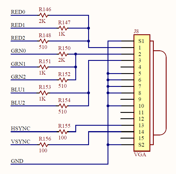
I have a Spartan 3E board and I am working on a graphics project with the VGA controller. The userguide only mentions that 8 colors are possible. Is there any way I can generate more colors? Please let me know.
Thanks
I have a Spartan 3E board and I am working on a graphics project with the VGA controller. The userguide only mentions that 8 colors are possible. Is there any way I can generate more colors? Please let me know.
Thanks
 <
<