Continue to Site

Welcome to EDAboard.com

Welcome to our site! EDAboard.com is an international Electronics Discussion Forum focused on EDA software, circuits, schematics, books, theory, papers, asic, pld, 8051, DSP, Network, RF, Analog Design, PCB, Service Manuals... and a whole lot more! To participate you need to register. Registration is free. Click here to register now.

Guidence to design a Op amp stage please?

Status
Not open for further replies.

UroBoros

Advanced Member level 2
Joined
May 5, 2004
Messages
642
Helped
19
Reputation
38
Reaction score
8
Trophy points
1,298
Location
Cochin - India
Activity points
6,463
op amp stages

Hello


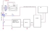
I need to measure current through R1 by measuring the voltage across it. Range is 0 to 500mA current.

I propose to use a .1 or .2 ohm resistor there.
So voltage developed will be from 0 to 50millivolt or 100 millivolt.

I need a resolution of .1mA .So plans to drive MCP3304 in pseudo differential mode.

The voltage range I need to obtain at the input of ADC is 1 volt to 4 volt.

Please give some guidelines to derive my design.
I am using Proteus to simulate my design.(Learning)

Thanks a lot
 

sense resistor example op-amp

You will need an instrumentation amplifier or a low side current sense amplifier. Chose the gain and output reference voltage to cope with the dynamic range of your ADC.
 

    UroBoros

    Points: 2
    Helpful Answer Positive Rating
op07 current sense

If your maximum current to measure is only 500mA, maybe you can use a higher value resistor. It will cause some more power loss, but it will be much more easy to reach the 0.1mA required precision.

For example in your circuit, 80V*0.5Amps = maximum 40Watt. If you use a 1 Ohm sense resistor, you lose 1Ohm*(0.5^2) = 0.25Watt. Still rather small loss with respect to the 40Watts. Be careful anyway, because you need to subtract the 0.5Volt on the sense resistor from the gate-drive voltage.
 

    UroBoros

    Points: 2
    Helpful Answer Positive Rating
Thanks for the help
svhb said:
If your maximum current to measure is only 500mA, maybe you can use a higher value resistor. It will cause some more power loss, but it will be much more easy to reach the 0.1mA required precision.

Could you brief on why better accuracy with high value resistor?

Thanks
 

I know from experience (and theory) that it is easier to obtain your 0.1mA resolution when you start from a higher input voltage :
- if you have 0 - 50mV input (0-500mA), you need to amplify 80 times with a very low offset voltage opamp (less than 0.01mV/80 = less than 125nV)
- if you have 0-500mV input, you need to amplify only 8 times, and maybe can get away with an opamp that has an offset of less than 0.1mV/8=12.5µV

The question is if the 0.1mA states is the resolution or the accuracy? With accuracy, I mean that with all possible tolerances, the 0.1mA is the maximum error measured. With resolution, I mean the minimum possible difference between two output values of your ADC (for example in this context, a 12 bit ADC gives you a resolution of 500mA/4096 = 1.2mA).

Probably, you don't need the absolute accuracy of 0.1mA. But this is up to your specifications.

Stefaan
 

    UroBoros

    Points: 2
    Helpful Answer Positive Rating
svhb said:
I know from experience (and theory) that it is easier to obtain your 0.1mA resolution when you start from a higher input voltage :
- if you have 0 - 50mV input (0-500mA), you need to amplify 80 times with a very low offset voltage opamp (less than 0.01mV/80 = less than 125nV)
- if you have 0-500mV input, you need to amplify only 8 times, and maybe can get away with an opamp that has an offset of less than 0.1mV/8=12.5µV
Got it. So I change my plan. My shunt resistor is .5 Ohms. So I get a drop of 0 to 250mVolts. I use OP07 opamp with a gain of 10. Its offset is 80uVolts. So total offset is .8mVolts
So my output from 1st opamp stage varies from .8mVolts to 2.5008Volts.(Am I correct?)
My ADC is is pseudo differential mode with reference 2.048V. (13 bit ADC MCP3304) So one division is 500uVolts. Now I have .8 to 2500.8 mVolts span signal which is 500uVolts*5000 Divisions which is .1mA resolution, not accuracy. Now I need to place this 2.5Volt span equally spaced around 2.048Volts referrence to get 5000 values. Here I use another OP07 to offset this signal to .798V to 3.298V. Then low passfilter multiplexor and ADC.
This is my plan. Is the strategy workable? I will post schematics later.
svhb said:
The question is if the 0.1mA states is the resolution or the accuracy? With accuracy, I mean that with all possible tolerances, the 0.1mA is the maximum error measured. With resolution, I mean the minimum possible difference between two output values of your ADC (for example in this context, a 12 bit ADC gives you a resolution of 500mA/4096 = 1.2mA).
I am talking about resolution.Sorry for confusion. To be frank accuracy is not that much critical for me.

Thanks for the time

Added after 2 hours 16 minutes:

Here is my schematics in proteus
0 current mode


full current mode
 

Maybe it is better to use an N-channel mosfet and leave it below the load (like in your first post). It will be easier to drive, and will be cheaper. The 0.25V across your sense resistor is low enough to not disturb the gate drive.
 

    UroBoros

    Points: 2
    Helpful Answer Positive Rating
Status
Not open for further replies.

Similar threads

Part and Inventory Search

Welcome to EDABoard.com

Sponsor

Back
Top