Continue to Site

Welcome to EDAboard.com

Welcome to our site! EDAboard.com is an international Electronics Discussion Forum focused on EDA software, circuits, schematics, books, theory, papers, asic, pld, 8051, DSP, Network, RF, Analog Design, PCB, Service Manuals... and a whole lot more! To participate you need to register. Registration is free. Click here to register now.

Measure current in an electrolysis process

Status
Not open for further replies.

UroBoros

Advanced Member level 2
Joined
May 5, 2004
Messages
642
Helped
19
Reputation
38
Reaction score
8
Trophy points
1,298
Location
Cochin - India
Activity points
6,463
electrolysis mosfet

Hello

I need to measure the current in a electrolysis process. Maximum current is 500ma. I need to monitor the current continuously for over current etc. I need 9 channels.

I am not having very good idea on how to do the hardware part .PIC software I can manage.
This is the image i propose to get an idea of my requirement
48_1232342530.jpg


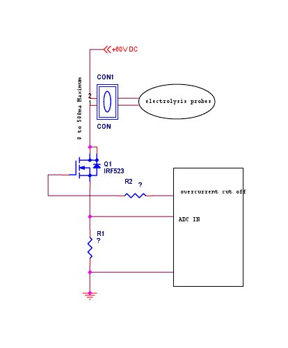
If my required range is 0to 500ma can somebody help me with good hardware design suggestions. I need to measure 9 channels like this .But I think i can do it by analogue multiplexer chips. Also suggest a chip for my purpose.
Please suggest a a suitable series resistor to make PIC calculation simple. I need only a resolution of 1mA.
Thanks
 

chevymn1964 said:
Check out the MAX4080SASA... Its a current sense IC & It works great
Thanks for the link.
My problem is I need to implement this for 9 channels in my system. So footprint and cost is a issue. More than that I do not need high precision . The shunt resistor voltage measurement method will do my purpose. I believe!

Thanks
 

Hi Roy,
check the attachment.
 

    UroBoros

    Points: 2
    Helpful Answer Positive Rating
take care of resistor wattage
 

    UroBoros

    Points: 2
    Helpful Answer Positive Rating
The circuit would require a MOSFET with sufficient voltage rating and logic-level gate drive, to allow control from a PIC. IRF523 (not an active part BTW) has neither.

The shunt voltage drop further reduces gate drive voltage, thus it has to be designed sufficient low, e. g. 500 mV using an 1 ohms shunt. For 1 mA resolution, the shunt voltage has to be amplified to at least 2.5 volt.
 

    UroBoros

    Points: 2
    Helpful Answer Positive Rating
FvM said:
The circuit would require a MOSFET with sufficient voltage rating and logic-level gate drive, to allow control from a PIC. IRF523 (not an active part BTW) has neither.

The shunt voltage drop further reduces gate drive voltage, thus it has to be designed sufficient low, e. g. 500 mV using an 1 ohms shunt. For 1 mA resolution, the shunt voltage has to be amplified to at least 2.5 volt.

Thanks Amith for the schematics.
Forget about MOSFET, Can I use a PNP transistor because of the dropping resistor? Max only 500ma so why cant we go with a transistor?

Thanks
 

Not PNP but a NPN with sufficient current gain at 500 mA would be reasonable.
 

    UroBoros

    Points: 2
    Helpful Answer Positive Rating
FvM said:
Not PNP but a NPN with sufficient current gain at 500 mA would be reasonable.

I meant to use PNP with shunt in collector so that it wont effect switching.

btw one change in requirement.

I need .1mA resolution upto 500mA. (Total 5000 ADC divisions)
Which is a reasonabily prized chip for my purpose?
I need 14 bit ADC in that case.
Regards
 

Hello

I have drawn a circuit to switch my probes.
btw I am learning Proteus also. I have simulated this circuit in Proteus and seems to be working as required.(As far as I know about simulation)
Please suggest the consequences of my plan if any. Since I was not able to locate the part number of LOGIC level MOSFETs widely available,I was not able to select one from my local market. But from IRF520 data sheet I felt it can conduct my currents (Less than 1 amps) at 5V in gate.(Right?)
This is my design.


Thanks
 

Status
Not open for further replies.

Similar threads

Part and Inventory Search

Welcome to EDABoard.com

Sponsor

Back
Top