Continue to Site

Welcome to EDAboard.com

Welcome to our site! EDAboard.com is an international Electronics Discussion Forum focused on EDA software, circuits, schematics, books, theory, papers, asic, pld, 8051, DSP, Network, RF, Analog Design, PCB, Service Manuals... and a whole lot more! To participate you need to register. Registration is free. Click here to register now.

finding Phase angle between voltage and current

Status
Not open for further replies.

umery2k75

Advanced Member level 1
Joined
Apr 19, 2006
Messages
434
Helped
41
Reputation
80
Reaction score
15
Trophy points
1,298
Location
Pakistan
Activity points
5,748
poor power factor da controller

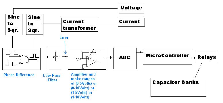
I need to make up the Power Factor Controller for the final year project. Actually that's my friend project. He got around 6 months to compete that project, but he couldn't with group of 4 people, they had done nothing in the project so far. Now their group leader is asking me to complete his project. I believe his knowledge of electronic is poor, but on the other hand he has the highest grades achieved so far in graduation. I'll be free on 16th May 08 and their submission is on 19th May 08. I don't have enough time to carry up the research work on this. Friend of mine told me that somebody advises him to use a small matrix of capacitor on the line load and with help of relays switch them. Measure up the voltage and current phase difference and calculate the offset, according to the offset values switch capacitors accordingly with microcontroller or something.He told me he'll use the Current transformer for that. The load would be made by the autotransformer, those guys purchased the autotransformer working from line frequency. He said, it's kind of dummy inductive load for that. In short, the purpose is that when the inductive load on the line increases, the capacitors get connected on the line with relays.He also said they'll also have a zero cross detector.
I appreciate if anybody could help me as how to implement it in the block form. I'll make the circuit for that or if you have any circuit schematic on that, that would be very helpful. It's not my work so I'm not worried.Neither I care whether this final year project will be completed within 2-3 days or not! I'll try my best to make up their project.
 

control relay and measure power factor

Yes, industrial reactive power compensation with switched capacitor banks works as you described. It's standard component in power distribution systems since decades.

Basically it consist of three parts: A reactive power measurement, a controller (not necessarily a microcontroller, has been pure electro-mechanical in the past) and a capacitor bank with contactors.
 

Re: Power Factor Controller

Hi,
Don't worry, they must have passed out or failed already. Think of the juniors now. And for junior's sake:

What you need to do is to measure the phase angle between the system voltage and current which will be lagging without any capacitance connected. I suppose you can do this easily using some of the energy meter ICs ( or may be phase angle ICs also may be there?). Then the controller should then switch On/OFF the capacitors to/from the line to minimise the phase angle.

Regards,
Laktronics
 

Power Factor Controller

For current:
Current transformer(properly loaded) feeding a crossover detector

For voltage:
Voltage feeding a cross over detector

mesure difference of time and program acting upon it

Cross overs;
========
Sychronized on a climbing wave(1 diode each)
Pic micro Comparators fed by opto insulators for safety.
I have used that in the past (not for PF )
 

Re: Power Factor Controller

Thanks for the replies
@Laktronics
No they aren't failed/neither passout, they are coming to my home on monday, they don't even have bought capacitor banks and other necessary things and not even line voltage relays.There group leader told me that they had done all the necessary simulations on computer.Simulation is not necessary. They were using the zero cross detector in the circuit, while having a discussion with my teacher long ago. Teacher advises me not to use the zero cross detector, as this some times detects it wrong, because of noise, it sometimes triggers it wrong.So he told me to convert the sine wave into a digital pulse and then use it in your circuit, because if line becomes noisy as it had happened to him, the trigger circuit that is detecting the sine wave to cross the zero might malfunction. So he told me to convert sine into Square wave like in TTL, then do what you want to do with the TTL square signal. It will be free of noise.

This the post by another guy(desertKids) on Power Factor Controller:

hey guy...actually i had do this project before..but i named it powe factor corrector..i think it same with what you want.bt now i can't find da circuit that i draw before..but i can tell you the theory la..

1st use a hall effect current transducer/current transformer to measure ac current from voltage source...then use a comparator/schmitt trigger to change both voltage and current signal from sine wave to pulse wave...so now use a XOR gate to XOR the two voltage and current pulse wave...so you can get the phase different of voltage and current...so now built a pulse wave generator using 555 timer...pulse width around 10ms..depend on you..so AND the signal of 555timer and phase difference from XOR gate...so you can get a pulse wave that represent how much degree of phase difference,(for my project is 1 pulse = 10degree), so now need use a counter that able to count how many pulse in an intrval ( 100ms for my project ).then use the signal from counter to select relay to switch on which capacitor that you want to use...

actually i just built up my 1st prototype then i stop it already...my 1st prototype can funtion but not so nice..hope the infomation i give can help you...and i wil upload the schmetic that i drawn when i find it bc...all the best...(i use 1 month to do this)
 

Power Factor Controller

The sine waves ARE being converted to "square wave "by using a voltage large enough feeding through a resistor going to a diode detecting when this "really slightly trapezoidal wave is smaller than the lowest reference voltage of the Pic COMP
If super safety is needed !!!
there is the WDT and also a redondancy approach(twin system)possible......
I honestly cannot see that noise could affect that....
 

Re: Power Factor Controller

The comparator and XOR circuit is very simple robust phase detector indeed. I'have used it previously to monitor the phase of audio signals.

However, for reactive power compensation, I think it's more important to measure the reactive current component as a signed value rather than the phase angle or power factor as input value for the controller. This value may be monitored additionally.

The reactive current directly maps to a number of capacitors to be switched on or of, while the real current is basically unimportant for the controller.

A measuring circuit for reactive current can be made from a 90° phase shift for voltage reference input (an integrator is favoured as it also suppresses harmonics), a comparator and a synchronous rectifier (or demodulator).

A principial circuit for a synchronous rectifier is shown below.


Re: Power Factor Controller

switch capacitors accordingly with microcontroller or something.He told me he'll use the Current transformer for that. The load would be made by the autotransformer, those guys purchased the autotransformer working from line frequency. He said, it's kind of dummy inductive load for that. In short, the purpose is that when the inductive load on the line increases, the capacitors get connected on the line with relays.He also said they'll also have a zero cross detector


This shows clearly what they want ..I think .:?:
So it would be an overkill to use a signed phase value , as it will always (in this case) in the same direction.
The higher the load on the transformer the closer to 1 cos Phi will be......
 
  • Like
Reactions: pwe018

    pwe018

    Points: 2
    Helpful Answer Positive Rating
Re: Power Factor Controller

A transformer (may be an auto- or isolation transformer) has mainly reactive idle current, but only a few % of nominal load current. So the transformer is a light load that sinks only small amounts of reactive power.

The system specification shouldn't be defined from an existing test load but from real load cases, e. g. asynchronous induction motors used in HVAC or electrical machines.
 

Power Factor Controller

Oups !
Correct , FvM !

My mistake..Theory long time gone by....
 

Re: Power Factor Controller

Here is the idea that I have on my mind for implementing it.I had a chat with their group leader and he told me that they had to use the microcontroller and he told me that they had mention the name of 89C51. He told me it doesn't matter what the controller is doing, even if it's just flashing up the few LEDs, but it has to be there or it would be soldered into the board with no connection with other circuit it would look as if the controller is functioning in the circuit, but there won't be any program in it's EPROM and it won't be running and won't have the power connection, because those guys have submitted their final year project file before even they made up the project :D, they had made final 6 copies of project file and had submitted them to their Internal Project Advisor, External Project Advisor, and other four for themselves, as they are four.
But please, share any idea that you have on that, if you have any idea that's related to the analog, please do share it. Don't pose any restriction on Power Factor Correction by involving any (8,16,24,n bit Controller).


Re: Power Factor Controller

When using the phase angle or power factor as controller input, you have a varying control process gain, depending on the unknown real power. Switching a single capacitor can either result in a few % or full scale change of power factor.

The misunderstanding is probably suggested by the term power factor controller. Actually it's rather a reactive power compensator. Using reactive power respectively current as controller input, you get constant control process gain and easy and stable controller operation.

Apart from general considerations, what's a suitable input measurement for a power factor controller, your design has to be supplemented to my opinion. It is unable to determine the power factor sign, an additional flip-flop is required to achieve this.

P.S.: To consider state of the art for your design, see the manual of an industrial standard power factor controller. It has interesting features as automatic identification of connected capacitors.
 

Re: Power Factor Controller

Hi umery2k75
Never replied any posts before but this one i think should be replied
I had my Final project Reactive Power Control. I simulated my idea in PSCAD, Did designed hardware that never worked actually i did not worked hard enough for that. I'm uploding it, hope it will help you. I'm very casual on eda board my e mail is usmansarwar2004@yahoo.com
 

Is it possible to improvepower factor using Capacitors?
Which type of capacitor shall I use. After a longtime of googling I am in confusion now.
Where I can such a capacitor?
 

Status
Not open for further replies.

Similar threads

Part and Inventory Search

Welcome to EDABoard.com

Sponsor

Back
Top