Continue to Site

Welcome to EDAboard.com

Welcome to our site! EDAboard.com is an international Electronics Discussion Forum focused on EDA software, circuits, schematics, books, theory, papers, asic, pld, 8051, DSP, Network, RF, Analog Design, PCB, Service Manuals... and a whole lot more! To participate you need to register. Registration is free. Click here to register now.

Balun problem in ADS, plz help!

Status
Not open for further replies.

ye_zhongh

Junior Member level 1
Joined
Jan 25, 2008
Messages
19
Helped
0
Reputation
0
Reaction score
0
Trophy points
1,281
Activity points
1,413
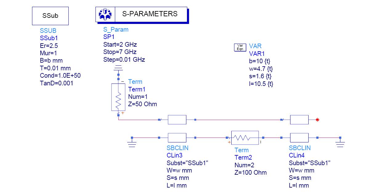
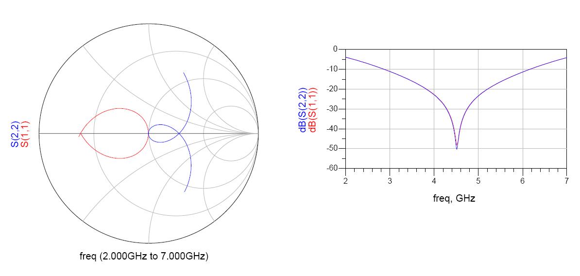
I am trying to design a bluetooth balun. I tried to achieve it in ADS. But I can't make the s-parameter right. I used the tuning tool in ADS. I changed all the variables, and I found that the input return loss and the output return loss conflicted with each other. According to the Marchand theory, it shouldn't happen. I am wondering why. Could you help me? Thanks very much in advance.

Here is a picture of my circuit:


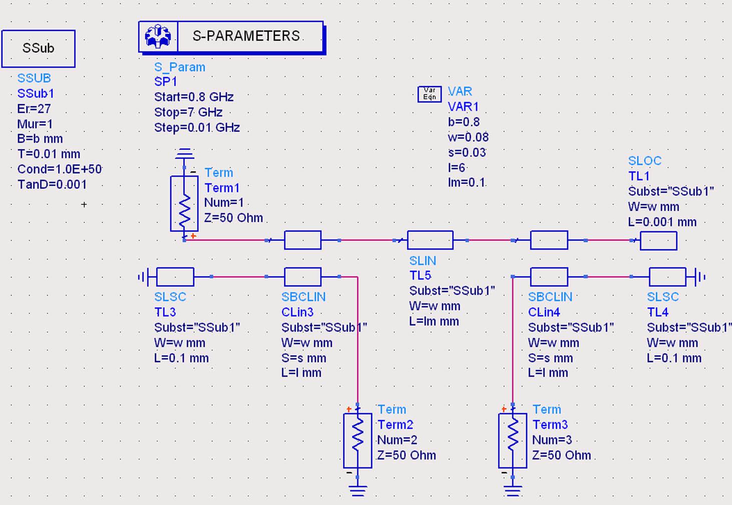
And I also attached the circuit.
 

A Marchand has good return loss over only an octave. It is only perfectly matched at one point. I changed a few dimensions and here is one tuned to 4.5 GHz.


    ye_zhongh

    Points: 2
    Helpful Answer Positive Rating
toonafishy said:
A Marchand has good return loss over only an octave. It is only perfectly matched at one point. I changed a few dimensions and here is one tuned to 4.5 GHz.


Thank you for help
But still I have some questions about your circuit. Balun has three ports, but you just put two ports in the circuit, why? And the value of term2 is 100ohm, why? If I want to have a look at the phase difference between the two outputs, how can I make it?
 

The balun is really a two port device. The output is balanced (differential mode), the input is single ended grounded (common mode). That is the reason for using a balun. The balun has a 1:2 impedance ratio. The single ended 50 ohms input is transformed to a 100 ohm differential output. The way you draw it in your schematic is somewhat artificial. The way I draw it is how it is actually used.
 

    ye_zhongh

    Points: 2
    Helpful Answer Positive Rating
toonafishy said:
The balun is really a two port device. The output is balanced (differential mode), the input is single ended grounded (common mode). That is the reason for using a balun. The balun has a 1:2 impedance ratio. The single ended 50 ohms input is transformed to a 100 ohm differential output. The way you draw it in your schematic is somewhat artificial. The way I draw it is how it is actually used.

can you recommend me some books or papers introducing balun basicly? Maybe I am still not very clear about the concepts of balun.

And still the same question: according to your circuit, if I want to take a look at the phase difference between the two balanced outputs, how can I make it?

Thank you.
 

To measure the phase difference at balanced port make an ac simulation sweeping single end port freq and probing the differential phase at output with the same load (100 Ohm).
Mazz
 

Mazz said:
To measure the phase difference at balanced port make an ac simulation sweeping single end port freq and probing the differential phase at output with the same load (100 Ohm).
Mazz

I will very appreciate if you can give me a ads circuit. I am still puzzled about it.
Thank you.
Tomek
 

Sorry, I'm not able to give you the circuit.
Please consider that the solution I'm giving is a very simple one.
Mazz
 

Never mind, thank you anyway
 

Status
Not open for further replies.

Part and Inventory Search

Welcome to EDABoard.com

Sponsor

Back
Top